Maintenance
See the separate component instruction manuals for individual component maintenance procedures.
Access to some system components requires that you remove the shields. The following steps are for shield removal. Shield replacement is the reverse of these steps, so make sure you take notes on the proper hose connections. Depending on your system, see the Parts Drawings on pages 11 and 13 for number
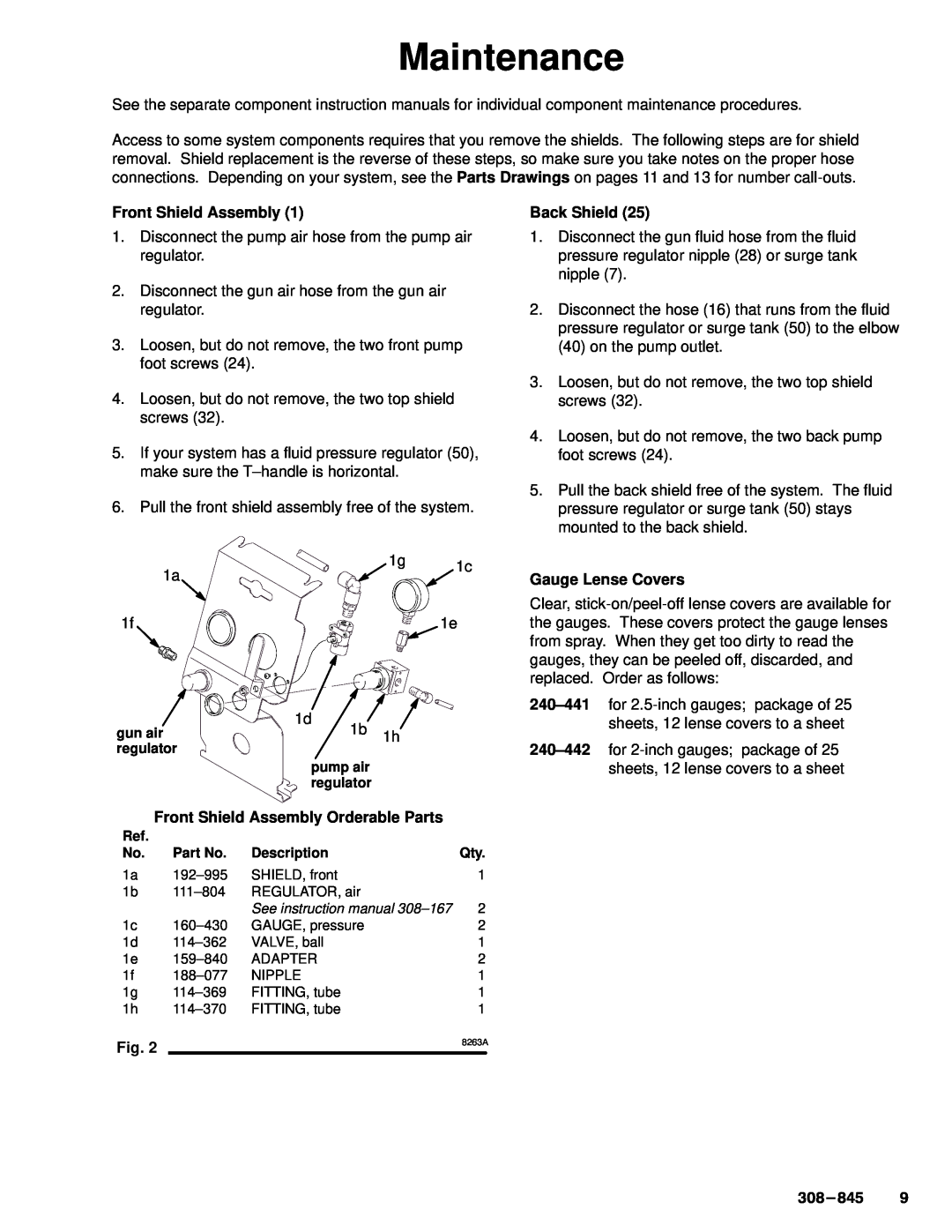
Front Shield Assembly (1)
1.Disconnect the pump air hose from the pump air regulator.
2.Disconnect the gun air hose from the gun air regulator.
3.Loosen, but do not remove, the two front pump foot screws (24).
4.Loosen, but do not remove, the two top shield screws (32).
5.If your system has a fluid pressure regulator (50), make sure the
6.Pull the front shield assembly free of the system.
Back Shield (25)
1.Disconnect the gun fluid hose from the fluid pressure regulator nipple (28) or surge tank nipple (7).
2.Disconnect the hose (16) that runs from the fluid pressure regulator or surge tank (50) to the elbow (40) on the pump outlet.
3.Loosen, but do not remove, the two top shield screws (32).
4.Loosen, but do not remove, the two back pump foot screws (24).
5.Pull the back shield free of the system. The fluid pressure regulator or surge tank (50) stays mounted to the back shield.
1a
1g 1c
Gauge Lense Covers
1f | 1e |
|
| 1d |
|
gun air |
| 1b 1h |
|
regulator |
|
| |
|
| pump air |
|
|
| regulator |
|
Front Shield Assembly Orderable Parts |
| ||
Ref. |
|
|
|
No. | Part No. | Description | Qty. |
1a | SHIELD, front | 1 | |
1b | REGULATOR, air |
| |
|
| See instruction manual | 2 |
1c | GAUGE, pressure | 2 | |
1d | VALVE, ball | 1 | |
1e | ADAPTER | 2 | |
1f | NIPPLE | 1 | |
1g | FITTING, tube | 1 | |
1h | FITTING, tube | 1 | |
Fig. 2 |
|
| 8263A |
|
|
| |
Clear,
