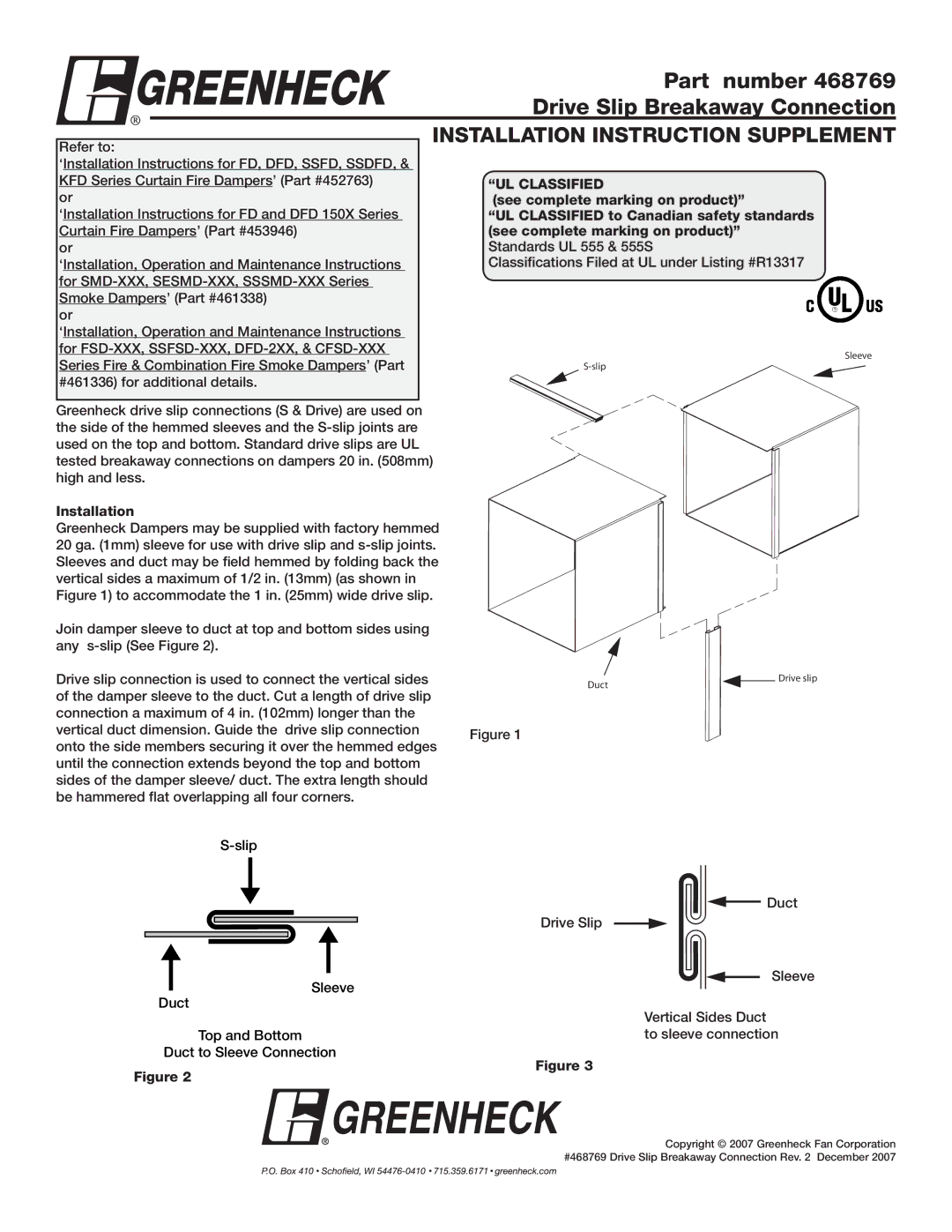
468769 specifications
Greenheck Fan 468769 is a prime example of innovation and efficiency in the realm of HVAC (Heating, Ventilation, and Air Conditioning) systems. This high-performance fan is engineered specifically to meet demanding ventilation needs while ensuring optimal energy consumption and quiet operation.One of the main features of the Greenheck Fan 468769 is its robust construction. Made from high-quality materials, this fan is designed to resist corrosion and withstand various environmental conditions. Its durable build not only extends the lifespan of the product but also ensures reliable performance over time.
Another significant characteristic of the 468769 fan is its advanced airflow design. The fan is equipped with an aerodynamic blade profile that maximizes airflow efficiency while minimizing noise levels. This design not only enhances performance but also contributes to a more comfortable work environment by reducing distractions caused by excessive operating noise.
The Greenheck Fan 468769 utilizes a direct drive motor, which streamlines the overall design and reduces maintenance needs. Direct drive systems eliminate the need for belts and pulleys, resulting in fewer moving parts that can wear over time. This translates to lower maintenance costs and less downtime for businesses relying on consistent ventilation.
Incorporating state-of-the-art motor technologies, the fan achieves high efficiency ratings that meet or exceed industry standards. The permanent split capacitor (PSC) motor employed in the 468769 model is designed for energy efficiency, producing high torque while consuming less electricity compared to traditional motors. This not only lowers operational costs but also makes the fan an environmentally friendly choice.
Moreover, Greenheck emphasizes versatility with the 468769 model. It can be customized to suit a wide range of applications, from industrial settings to commercial spaces. With adjustable speed options and various mounting configurations, users can tailor the fan to meet specific ventilation requirements, ensuring optimal air management for their unique environments.
In summary, the Greenheck Fan 468769 stands out in the HVAC market due to its combination of durability, innovative airflow design, efficient motor technology, and versatile applications. Organizations seeking a reliable and high-performing ventilation solution can strongly consider this model for its impressive features and benefits. As businesses increasingly prioritize energy efficiency and sustainability, the Greenheck Fan 468769 offers a smart investment that aligns with these goals.

