Damper Sizing Information
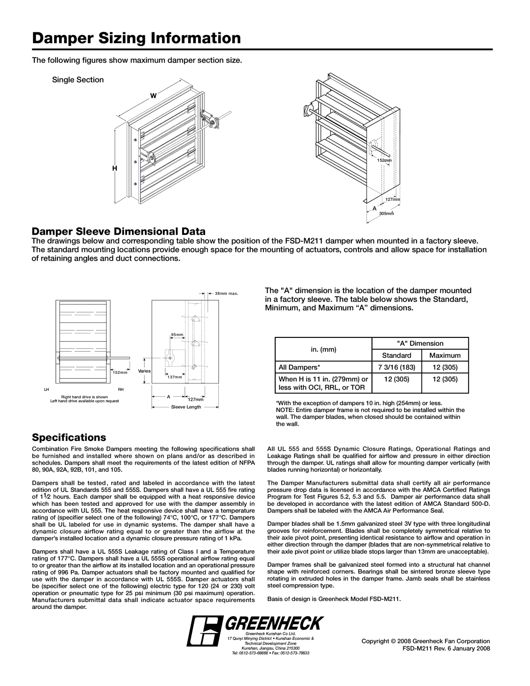
The following figures show maximum damper section size.
Single Section
W
152mm.
H
A
Damper Sleeve Dimensional Data
127.mm
305mm*
The drawings below and corresponding table show the position of the
|
|
|
|
|
| 38mm max. | The "A" dimension is the location of the damper mounted | |
|
|
|
| |||||
|
|
|
|
|
|
|
| in a factory sleeve. The table below shows the Standard, |
|
|
|
|
|
|
|
| |
|
|
|
|
|
|
|
| Minimum, and Maximum “A” dimensions. |
|
|
| 95mm |
|
|
|
|
|
|
| in. (mm) | "A" Dimension | |
|
|
|
| Standard | Maximum | |
|
|
|
|
| ||
| 152mm | Varies |
| All Dampers* | 7 3/16 (183) | 12 (305) |
|
|
|
|
| ||
|
| 137mm |
|
|
| |
|
|
| When H is 11 in. (279mm) or | 12 (305) | 12 (305) | |
|
|
|
| |||
LH | RH |
|
| less with OCI, RRL, or TOR |
|
|
Right hand drive is shown |
| A |
|
|
|
|
|
|
|
|
| |
Left hand drive available upon request |
|
|
|
|
|
| 127mm |
| *With the exception of dampers 10 in. high (254mm) or less. | |||
|
|
|
| Sleeve Length |
| |||||||
|
|
|
|
| NOTE: Entire damper frame is not required to be installed within the | |||||||
|
|
|
|
|
|
|
|
|
|
|
| |
|
|
|
|
|
|
|
|
|
|
|
| wall. The damper blades, when closed should be contained within |
|
|
|
|
|
|
|
|
|
|
|
| the wall. |
Specifications
Combination Fire Smoke Dampers meeting the following specifications shall be furnished and installed where shown on plans and/or as described in schedules. Dampers shall meet the requirements of the latest edition of NFPA 80, 90A, 92A, 92B, 101, and 105.
Dampers shall be tested, rated and labeled in accordance with the latest edition of UL Standards 555 and 555S. Dampers shall have a UL 555 fire rating of 11⁄2 hours. Each damper shall be equipped with a heat responsive device which has been tested and approved for use with the damper assembly in accordance with UL 555. The heat responsive device shall have a temperature rating of (specifier select one of the following) 74°C, 100°C, or 177°C. Dampers shall be UL labeled for use in dynamic systems. The damper shall have a dynamic closure airflow rating equal to or greater than the airflow at the damper’s installed location and a dynamic closure pressure rating of 1 kPa.
Dampers shall have a UL 555S Leakage rating of Class I and a Temperature rating of 177°C. Dampers shall have a UL 555S operational airflow rating equal to or greater than the airflow at its installed location and an operational pressure rating of 996 Pa. Damper actuators shall be factory mounted and qualified for use with the damper in accordance with UL 555S. Damper actuators shall be (specifier select one of the following) electric type for 120 (24 or 230) volt operation or pneumatic type for 25 psi minimum (30 psi maximum) operation. Manufacturers submittal data shall indicate actuator space requirements around the damper.
All UL 555 and 555S Dynamic Closure Ratings, Operational Ratings and Leakage Ratings shall be qualified for airflow and pressure in either direction through the damper. UL ratings shall allow for mounting damper vertically (with blades running horizontal) or horizontally.
The Damper Manufacturers submittal data shall certify all air performance pressure drop data is licensed in accordance with the AMCA Certified Ratings Program for Test Figures 5.2, 5.3 and 5.5. Damper air performance data shall be developed in accordance with the latest edition of AMCA Standard
Damper blades shall be 1.5mm galvanized steel 3V type with three longitudinal grooves for reinforcement. Blades shall be completely symmetrical relative to their axle pivot point, presenting identical resistance to airflow and operation in either direction through the damper (blades that are
Damper frames shall be galvanized steel formed into a structural hat channel shape with reinforced corners. Bearings shall be sintered bronze sleeve type rotating in extruded holes in the damper frame. Jamb seals shall be stainless steel compression type.
Basis of design is Greenheck Model
 GREENHECK
Greenheck Kunshan Co Ltd.
17 Qunyi Minying District • Kunshan Economic &
Technical Development Zone
Kunshan, Jiangsu, China 215300
Tel:
Copyright © 2008 Greenheck Fan Corporation