On belt drive units, centering can be accomplished by (a) loosening the inlet cone bolts to move the inlet cone or by (b) loosening the bearings in order to move the shaft.. Wheel and inlet cone overlap can be adjusted by loosening the wheel hub set screws and moving the wheel to the desired position.. Tighten all fasteners and set screws securely and realign drive pulleys after adjustment..
Approximate Wheel Clearance Dimensions
| Unit Size |
|
| SWB |
|
| SFD | SFB | ||
|
|
|
|
|
|
|
|
|
|
|
|
| SWB | SWB | SWB | Overlap | Overlap | Radial |
| Gap | Gap |
SFD | SFB | Tolerance | Gap |
| ||||||
Series | Series | Series |
|
|
|
| ||||
|
| 100 | 200 | 300 |
| inches (mm) |
|
| ||
|
|
|
|
|
|
|
| |||
|
|
|
|
|
|
|
|
|
|
|
6 |
| 106 | 206 |
| — | — | — |
| 3⁄8 (10) | — |
7..5 |
| 107 | 207 |
| — | — | — |
| 3⁄8 (10) | — |
9 | 9 | 108 | 208 |
| — | — | — |
| 1⁄2 (13) | 1⁄2 (13) |
10 | 10 | 110 | 210 |
| 3⁄8 (10) | 1⁄4 (6) | 5⁄32 (4) |
| 1⁄2 (13) | 1⁄2 (13) |
| 12 |
| 212 |
| 3⁄8 (10) | 1⁄4 (6) | 5⁄32 (4) |
| — | 1⁄2 (13) |
|
| 113 | 213 |
| 7⁄16 (11) | 1⁄4 (6) | 5⁄32 (4) |
| — | 1⁄2 (13) |
| 15 | 115 | 215 |
| 1⁄2 (13) | 1⁄4 (6) | 5⁄32 (4) |
| — | 1⁄2 (13) |
|
| 116 | 216 |
| 1⁄2 (13) | 1⁄4 (6) | 5⁄32 (4) |
| — | — |
| 18 | 118 | 218 |
| 5⁄8 (16) | 3⁄8 (10) | 5⁄32 (4) |
| — | 1⁄2 (13) |
| 20 | 120 | 220 |
| 5⁄8 (16) | 3⁄8 (10) | 5⁄32 (4) |
| — | 5⁄8 (16) |
| 22 |
| 222 |
| 11⁄16 (18) | 3⁄8 (10) | 5⁄32 (4) |
| — | 5⁄8 (16) |
|
| 124 | 224 |
| 3⁄4 (19) | 3⁄8 (10) | 5⁄32 (4) |
| — | — |
| 25 |
|
|
| — | — | — |
| — | 3⁄4 (19) |
| 27 |
|
| 327 | 7⁄8 (22) | 1⁄4 (6) | 3⁄16 (5) |
| — | 3⁄4 (19) |
| 30 |
|
| 330 | 15⁄16 (24) | 3⁄8 (10) | 3⁄16 (5) |
| — | 3⁄4 (19) |
|
|
|
| 333 | 11⁄16 (27) | 3⁄8 (10) | 3⁄16 (5) |
| — | — |
|
|
|
| 336 | 13⁄16 (30) | 3⁄8 (10) | 3⁄16 (5) |
| — | — |
|
|
|
| 340 | 11⁄4 (32) | 3⁄8 (10) | 1⁄4 (6) |
| — | — |
|
|
|
| 344 | 17⁄16 (37) | 3⁄8 (10) | 5⁄16 (8) |
| — | — |
|
|
|
| 349 | 19⁄16 (40) | 1⁄2 (13) | 5⁄16 (8) |
| — | — |
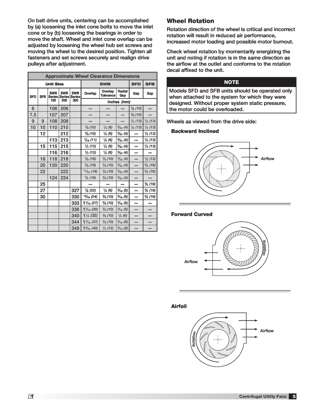
Wheel Rotation
Rotation direction of the wheel is critical and incorrect rotation will result in reduced air performance, increased motor loading and possible motor burnout..
Check wheel rotation by momentarily energizing the unit and noting if rotation is in the same direction as the airflow at the outlet and conforms to the rotation decal affixed to the unit..
NOTE
Models SFD and SFB units should be operated only when attached to the system for which they were designed.. Without proper system static pressure, the motor could be overloaded..
Wheels as viewed from the drive side:
Backward Inclined
Airflow
Forward Curved
R
o
t
a t i o n
Airflow
Airfoil
n o i t a t
o R
Airflow
®
Centrifugal Utility Fans 5