OPERATION
Two Blade Arm, Three Blade Disc & Disc (w/ Cutter Bits)
1)Check the attachment of the Grizzly to the carrier to ensure that all attachment point bolts and pins are in good order.
2)Check all hydraulic lines and connections for leaks and security.
3)Check the fluid level in the hydraulic tank.
4)Make sure the control vavle is in the "OFF" position.
Blade Arm/Disc - 1) Check the nuts holding the Blade Arm onto the shaft and the Blades onto the Blade Arm for tightness and make sure that the nuts are cotter pinned.
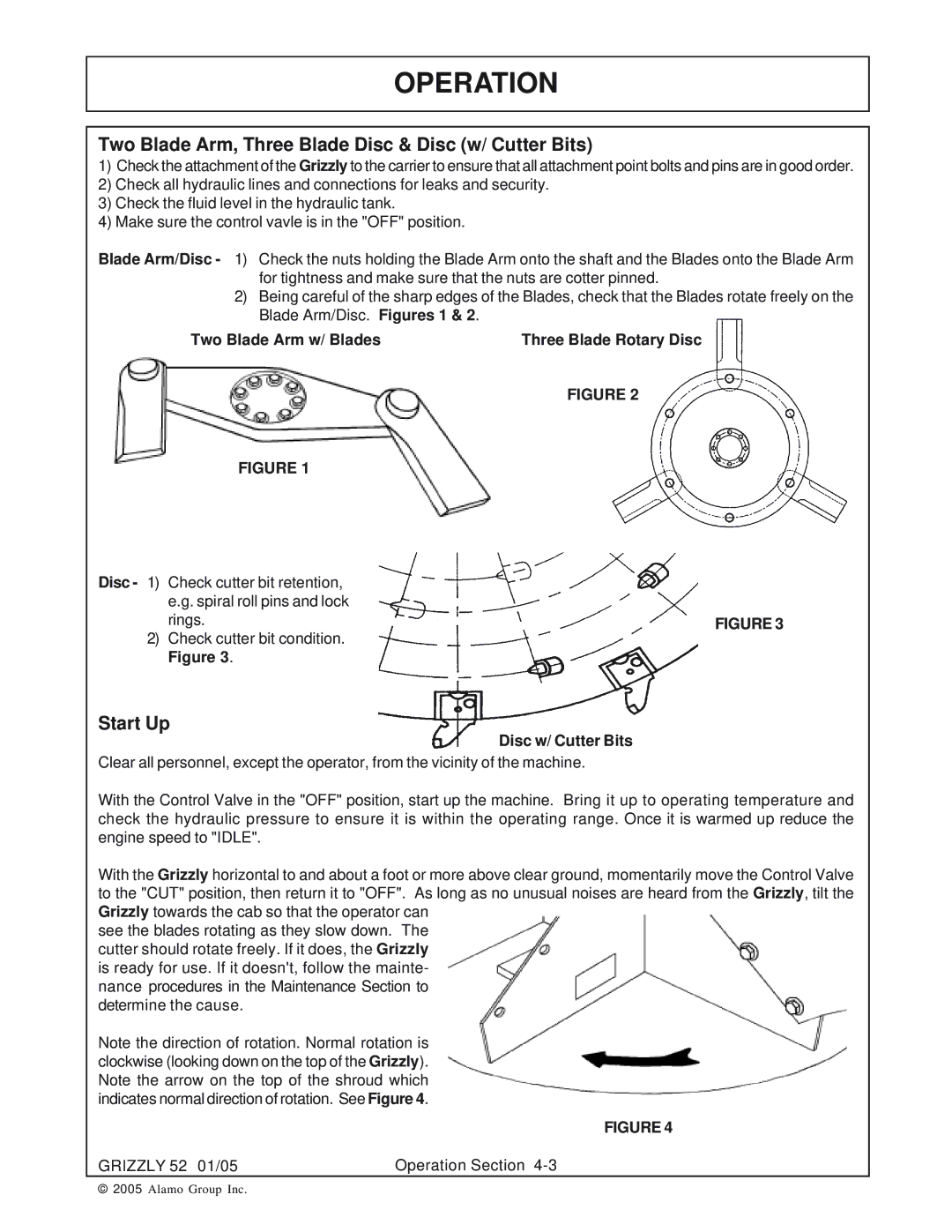
2)Being careful of the sharp edges of the Blades, check that the Blades rotate freely on the Blade Arm/Disc. Figures 1 & 2.
Two Blade Arm w/ Blades | Three Blade Rotary Disc |
FIGURE 2
FIGURE 1
Disc - 1) | Check cutter bit retention, |
|
| e.g. spiral roll pins and lock |
|
| rings. | FIGURE 3 |
2) | Check cutter bit condition. |
|
| Figure 3. |
|
Start Up
Disc w/ Cutter Bits
Clear all personnel, except the operator, from the vicinity of the machine.
With the Control Valve in the "OFF" position, start up the machine. Bring it up to operating temperature and check the hydraulic pressure to ensure it is within the operating range. Once it is warmed up reduce the engine speed to "IDLE".
With the Grizzly horizontal to and about a foot or more above clear ground, momentarily move the Control Valve to the "CUT" position, then return it to "OFF". As long as no unusual noises are heard from the Grizzly, tilt the Grizzly towards the cab so that the operator can
see the blades rotating as they slow down. The cutter should rotate freely. If it does, the Grizzly is ready for use. If it doesn't, follow the mainte- nance procedures in the Maintenance Section to determine the cause.
Note the direction of rotation. Normal rotation is clockwise (looking down on the top of the Grizzly). Note the arrow on the top of the shroud which indicates normal direction of rotation. See Figure 4.
FIGURE 4
GRIZZLY 52 01/05 | Operation Section |
© 2005 Alamo Group Inc.
