Connecting Tools |
| Air Control Valve |
|
|
|
|
|
|
Make sure the compressor model you use has sufficient cubic feet per minute (CFM) output for the air tool you plan to connect. Most air tools will have an air requirement stated in terms of a spe- cific CFM at a specific pressure (PSI). Consult the chart below to determine the output of your com- pressor model.
Model | HP | CFM | Tank |
|
| @ 90 PSI | Cap. |
|
|
|
|
G8294 | 2.0 | 3.0 | 7 gal |
|
|
|
|
G8295 | 2.5 | 3.5 | 11 gal |
|
|
|
|
G8889 | 2.0 | 4.2 | 4 gal |
|
|
|
|
The compressor should put out a higher CFM than the tool requires. If connecting multiple tools which will be used simultaneously, then the CFM for each tool should be added together and com- pared to the compressor output value.
Consideration should also be given to the type of usage. A nailer or staple gun uses air in short bursts and it is easier for the compressor to main- tain pressure. A paint sprayer or grinder tends to use a more continuous stream of air as these tools are run for longer time periods. It is always better to oversize a compressor to allow for vari- ation in the type of usage and the number of tools to be powered. Air tools being operated with insufficient air volume will not perform their func- tion satisfactorily.
Connect the tool using a good quality air line with an adequate length to reach from the compressor to the point of use.
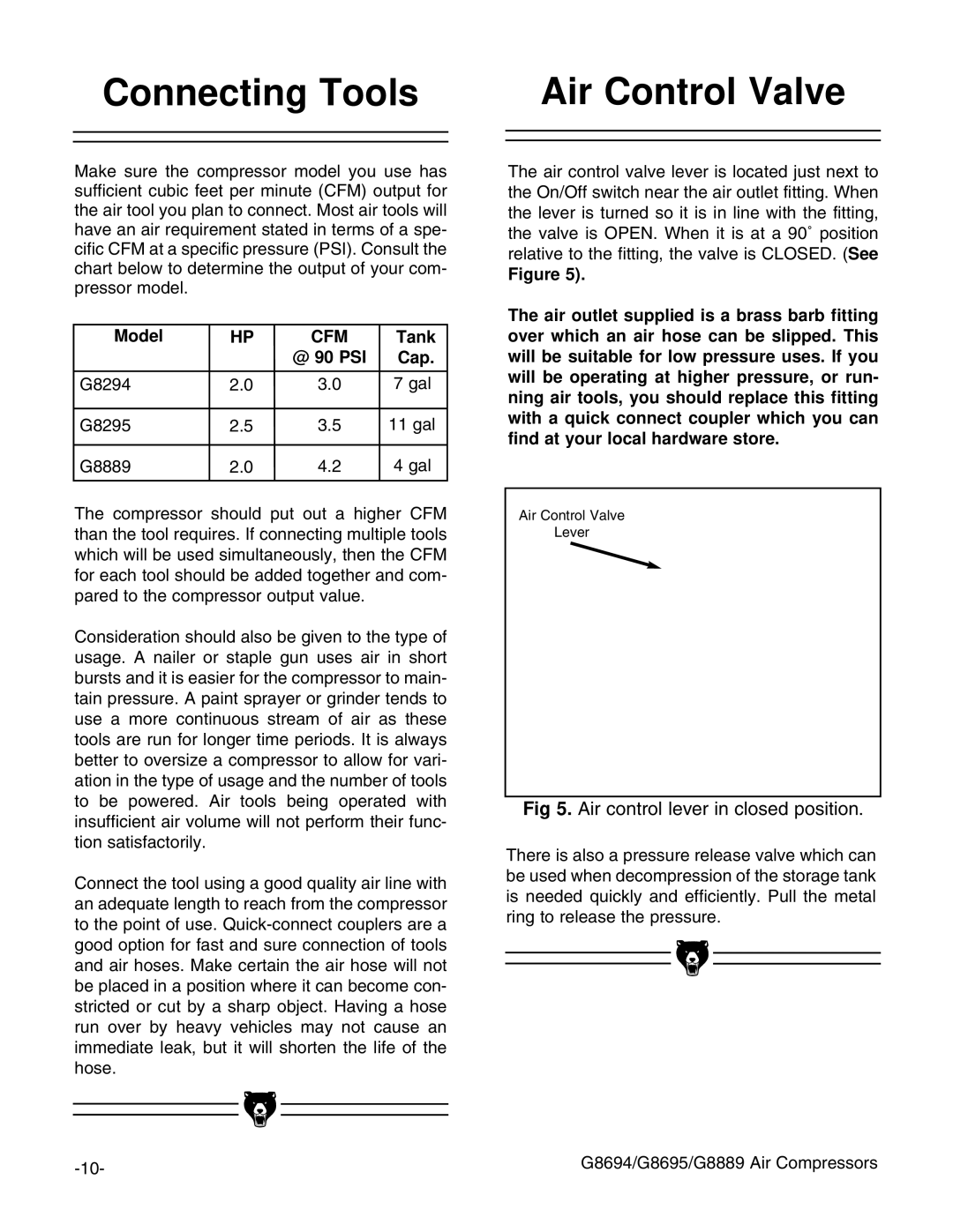
The air control valve lever is located just next to the On/Off switch near the air outlet fitting. When the lever is turned so it is in line with the fitting, the valve is OPEN. When it is at a 90˚ position relative to the fitting, the valve is CLOSED. (See
Figure 5).
The air outlet supplied is a brass barb fitting over which an air hose can be slipped. This will be suitable for low pressure uses. If you will be operating at higher pressure, or run- ning air tools, you should replace this fitting with a quick connect coupler which you can find at your local hardware store.
Air Control Valve
Lever
Fig 5. Air control lever in closed position.
There is also a pressure release valve which can be used when decompression of the storage tank is needed quickly and efficiently. Pull the metal ring to release the pressure.
|
|
| G8694/G8695/G8889 Air Compressors |
|
|
| |
|
| ||
|
| ||
|
|
|