16.With the main body loosely fastened (see Figure 6), move the slide block back and forth, by either pulling/pushing on the lead screw or turning the cross slide handwheel. Stop when the pin in the slide block can be inserted into the hole in the slide. Push the pin, refer to step 7 , into place to secure the slide block.
17.The dovetail ways of the cross slide must clear the top of the taper attachement and line up with the dovetails on the taper attach- ment. The holes in the taper attachment are oversized to allow for height adjustment. Adjust for clearance and check that the cross slide moves in and out, along its full range of motion, without increased resistance. When the slide moves unobstructed and smoothly, tighten the four mounting screws.
18.Assemble the top cover plate, removed in
step 6 , using the six philips head screws
(Figure 7).
Figure 7. Support Rod and Deadman Assembly.
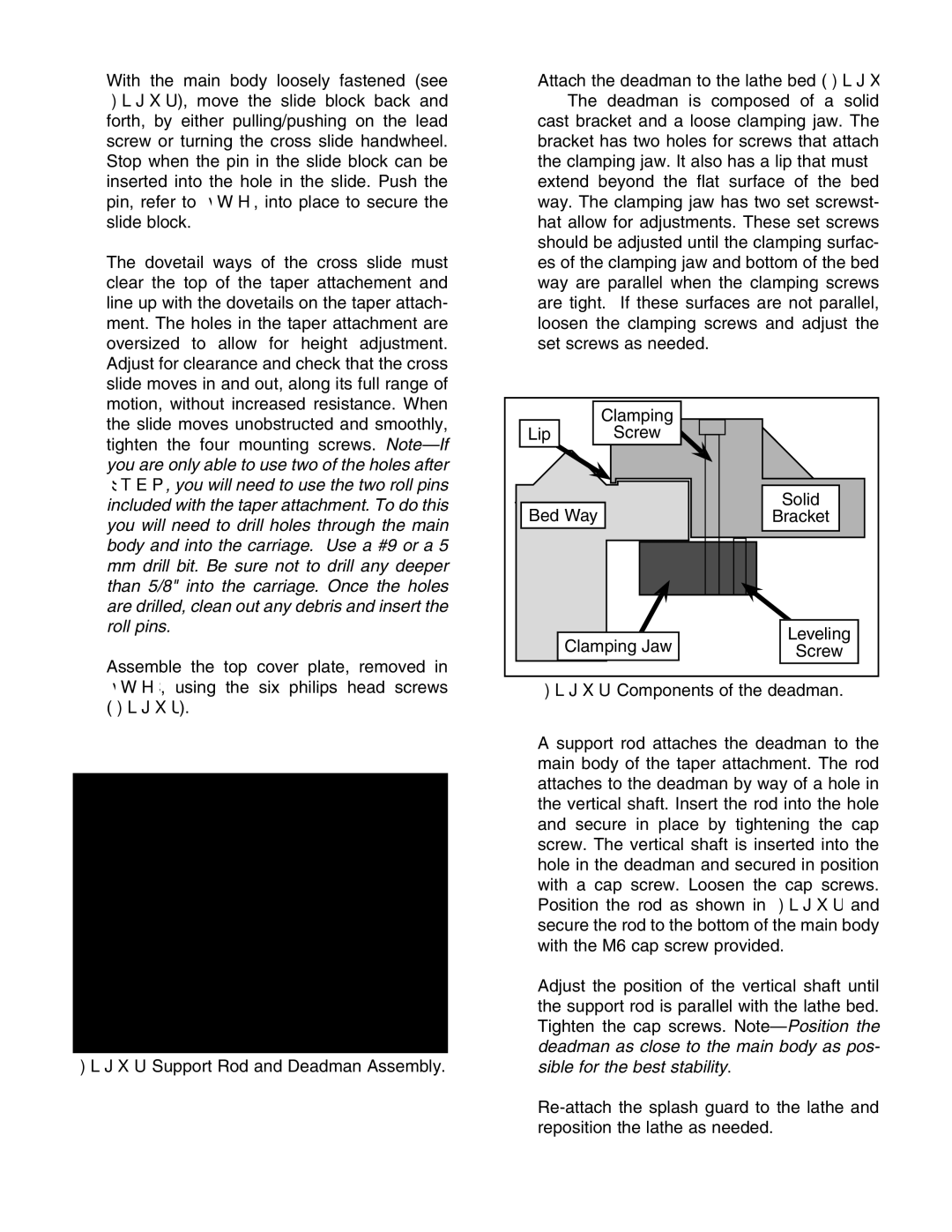
19.Attach the deadman to the lathe bed (Figure 8). The deadman is composed of a solid cast bracket and a loose clamping jaw. The bracket has two holes for screws that attach the clamping jaw. It also has a lip that must extend beyond the flat surface of the bed way. The clamping jaw has two set screwst- hat allow for adjustments. These set screws should be adjusted until the clamping surfac- es of the clamping jaw and bottom of the bed way are parallel when the clamping screws are tight. If these surfaces are not parallel, loosen the clamping screws and adjust the set screws as needed.
| Clamping |
Lip | Screw |
Bed Way | Solid |
Bracket |
Clamping Jaw | Leveling |
Screw |