To reduce risk of shock or accidental startup, always disconnect machine from power before adjustments, maintenance, or service.
Installing Riser Block
1.DISCONNECT BANDSAW FROM POWER!
2.Remove bandsaw blade (refer to the Owner's Manual included with your bandsaw). When finished, leave the wheel covers open.
3.Remove the
Power |
| |
Switch | ||
| ||
| Blade | |
Phillips | Guard | |
| ||
Screw |
| |
Double | Hex Bolt & | |
Nut | ||
Cord | ||
| ||
Clamp |
|
Figure 2. Components surrounding riser block.
4.Taking care not to disconnect any wiring, remove the power switch and the double cord clamp (Figure 2). Let the switch hang to the side for now.
Note: The switch is fastened in place with one screw above the box and one below it. Avoid removing the two screws on the face of the switch box, as this will open the switch box cover, exposing the wiring inside.
5.Remove the hex nut and bolt shown in Figure 2. With help from another person, lift the upper arm off the base casting.
IMPORTANT: Make sure all mating surfaces of riser block are clean before proceeding.
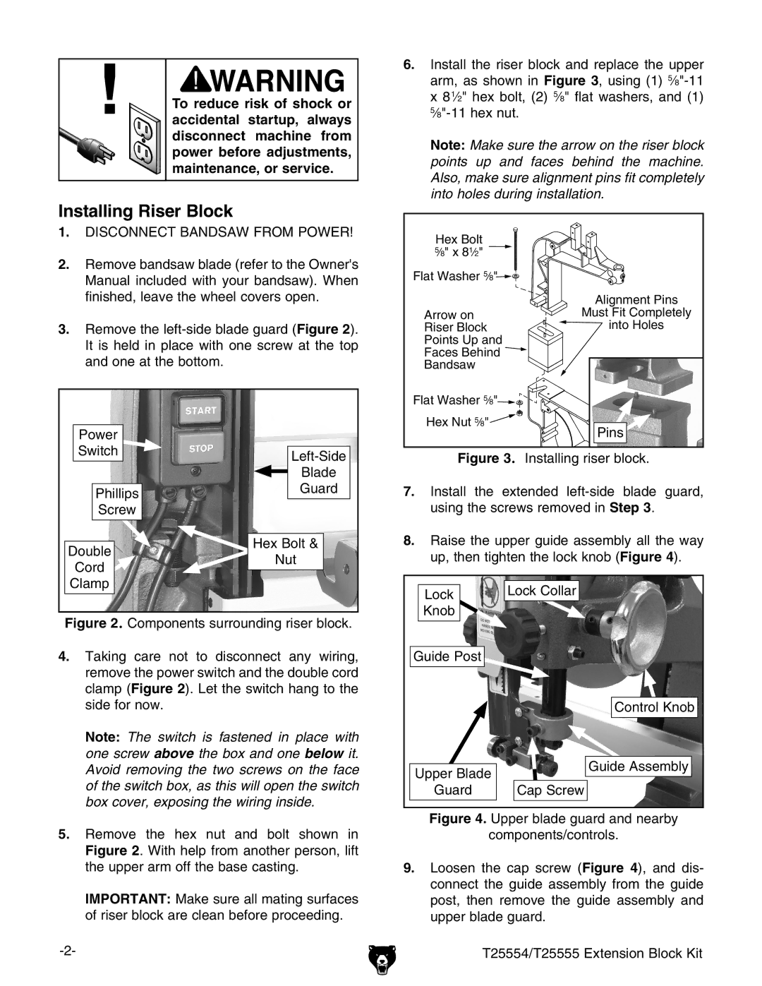
6.Install the riser block and replace the upper arm, as shown in Figure 3, using (1) 5⁄8"-11 x 8 1⁄2" hex bolt, (2) 5⁄8" flat washers, and (1) 5⁄8"-11 hex nut.
Note: Make sure the arrow on the riser block points up and faces behind the machine. Also, make sure alignment pins fit completely into holes during installation.
Hex Bolt
5∕8" x 81∕2"
Flat Washer 5∕8"![]()
![]()
| Alignment Pins |
Arrow on | Must Fit Completely |
Riser Block | into Holes |
Points Up and |
|
Faces Behind |
|
Bandsaw |
|
Flat Washer 5∕8"![]()
![]()
![]()
![]()
![]()
![]()
![]()
![]()
Hex Nut 5∕8"![]()
![]()
![]()
![]()
Pins
Figure 3. Installing riser block.
7.Install the extended left-side blade guard, using the screws removed in Step 3.
8.Raise the upper guide assembly all the way up, then tighten the lock knob (Figure 4).
Lock | Lock Collar |
| |
Knob |
|
Guide Post |
|
| Control Knob |
Upper Blade | Guide Assembly |
| |
Guard | Cap Screw |