10. Remove the guide post control knob and lock collar (Figure 4) from the pinion gear shaft.
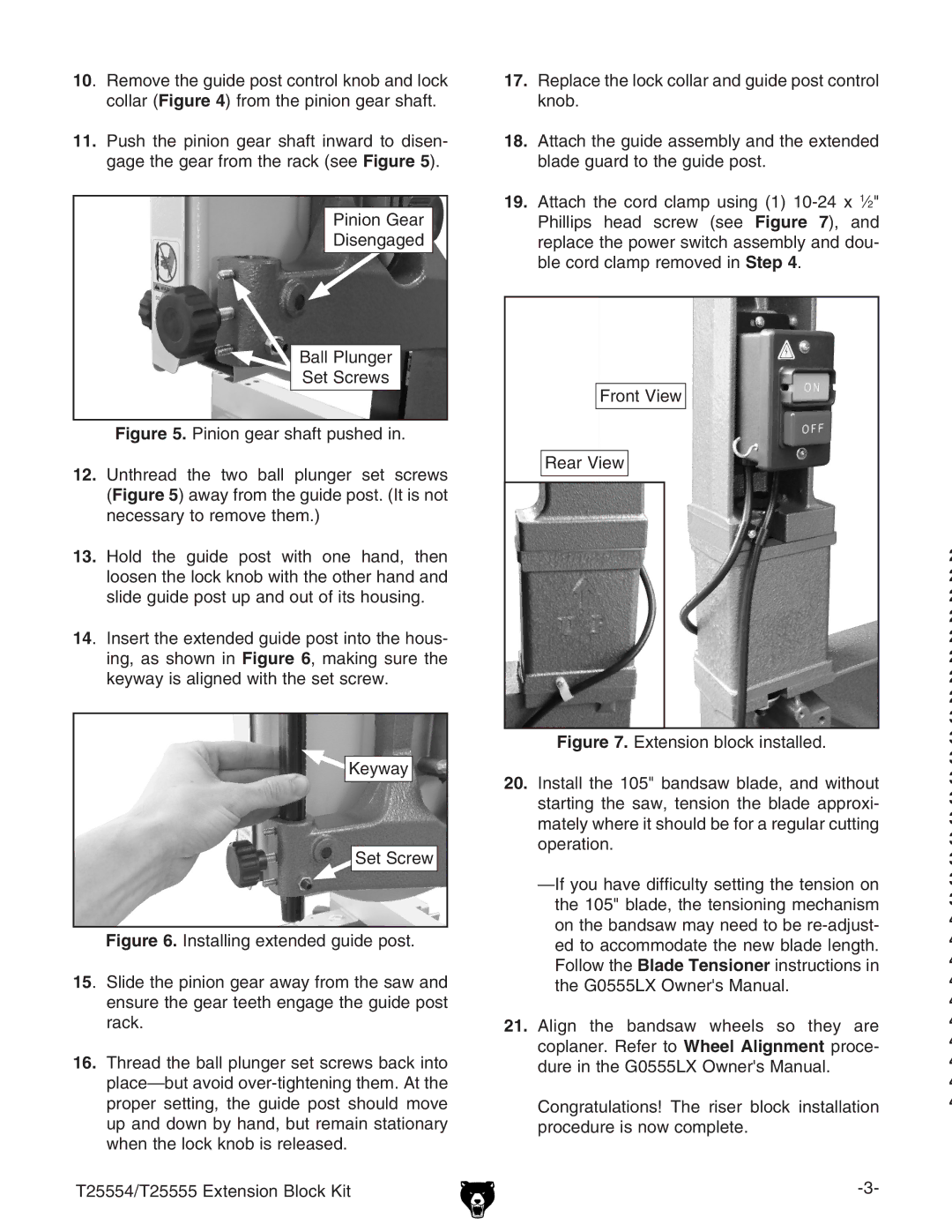
11.Push the pinion gear shaft inward to disen- gage the gear from the rack (see Figure 5).
Pinion Gear
Disengaged
Ball Plunger
Set Screws
Figure 5. Pinion gear shaft pushed in.
12.Unthread the two ball plunger set screws (Figure 5) away from the guide post. (It is not necessary to remove them.)
13.Hold the guide post with one hand, then loosen the lock knob with the other hand and slide guide post up and out of its housing.
14. Insert the extended guide post into the hous- ing, as shown in Figure 6, making sure the keyway is aligned with the set screw.

 Keyway
Set Screw
Figure 6. Installing extended guide post.
15. Slide the pinion gear away from the saw and ensure the gear teeth engage the guide post rack.
16.Thread the ball plunger set screws back into place—but avoid over-tightening them. At the proper setting, the guide post should move up and down by hand, but remain stationary when the lock knob is released.
T25554/T25555 Extension Block Kit
17.Replace the lock collar and guide post control knob.
18.Attach the guide assembly and the extended blade guard to the guide post.
19.Attach the cord clamp using (1) 10-24 x 1⁄2" Phillips head screw (see Figure 7), and replace the power switch assembly and dou- ble cord clamp removed in Step 4.
Front View
Rear View
Figure 7. Extension block installed.
20.Install the 105" bandsaw blade, and without starting the saw, tension the blade approxi- mately where it should be for a regular cutting operation.
21.Align the bandsaw wheels so they are coplaner. Refer to Wheel Alignment proce- dure in the G0555LX Owner's Manual.
Congratulations! The riser block installation procedure is now complete.
2
2
2
2
2
2
2
2
3
3
3
3
3
3
3
3
3
3
4
4
4
4
4
4
4
4
4
4