
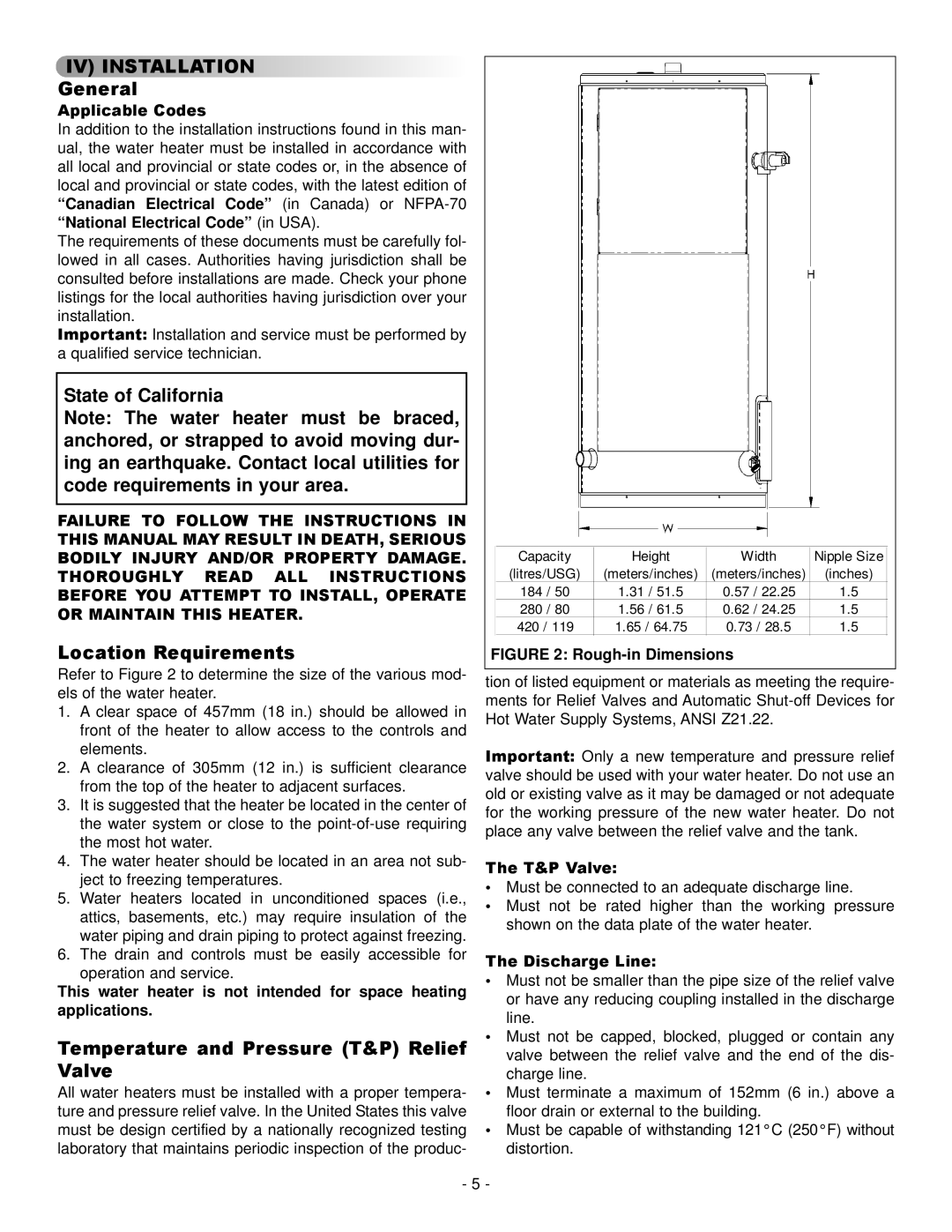
73992 specifications
GSW 73992, an innovative model in the world of advanced non-metallic materials, has garnered attention for its exceptional performance and unique characteristics. Engineered to meet the demanding needs of various industries such as aerospace, automotive, and construction, GSW 73992 stands out due to its remarkable properties and cutting-edge technologies.One of the main features of GSW 73992 is its lightweight nature. Weighing significantly less than traditional metal counterparts, this material enables designers and engineers to reduce overall weight without compromising structural integrity. This attribute is particularly advantageous in the aerospace sector, where weight savings translate into improved fuel efficiency and enhanced performance.
The technology behind GSW 73992 is grounded in advanced composite engineering. Utilizing a combination of high-strength fibers and resins, GSW 73992 exhibits exceptional tensile strength and impact resistance. Its ability to withstand harsh environmental conditions, including extreme temperatures and moisture, makes it a preferred choice for applications requiring durability and reliability.
Another standout characteristic of GSW 73992 is its corrosion resistance. Unlike metals, which can succumb to rust and degradation over time, GSW 73992 maintains its integrity even in challenging environments. This property not only contributes to the longevity of products made from GSW 73992 but also reduces maintenance costs, making it an economical option for manufacturers.
GSW 73992 also boasts excellent thermal insulation properties. Its low thermal conductivity ensures minimal heat transfer, making it ideal for applications in building materials and automotive components where temperature regulation is crucial. This feature enhances energy efficiency and contributes to sustainability efforts by reducing the need for additional insulation materials.
Additionally, GSW 73992 offers design flexibility, allowing manufacturers to create complex shapes and forms that would be difficult to achieve with traditional metals. This adaptability opens up new possibilities in product design, enabling creative solutions that can cater to specific industry needs.
Overall, GSW 73992 represents a significant advancement in material science, combining lightweight construction, high strength, resistance to environmental stressors, and design versatility. Its array of features positions it as a game-changer for industries seeking to improve performance while adhering to modern sustainability standards. As the demand for innovative materials continues to grow, GSW 73992 is poised to play a pivotal role in shaping the future of engineering and manufacturing.