GSW WATER HEATING Filling, Electrical Wiring, Temperature Regulation, Wiring Diagram, Danger

Models: WATER HEATING

1 7
Download 7 pages 46.43 Kb
Page 4
Image 4
Filling

tem, check valves must be installed to prevent the circulator from pumping hot water into another tank and overheating it.

8.The use of a pressure regulator is optional, but recom- mended when the cold supply pressure is over 80 psi. Reducing the inlet pressure to 45-60 psi will reduce probability of relief valve discharge by thermal expan- sion.

9.The water utility supply meter may contain a check valve, back-flow preventer or water pressure reducing valve. This will create a closed water system. During the heating cycle, the water expands creating a pressure build-up in the water system. A Temperature and Pressure (T&P) Relief Valve must be installed (150 psi maximum pressure). See preceding section. If the T&P valve discharges periodically, this may be due to ther- mal expansion in a closed system. To prevent this con- dition and to reduce the possible build up of lime on the Temperature and Pressure Relief Valve seat, either one of the following installations is required;

i)Install a 125 psi pressure relief valve in the cold water supply line. Make sure that the discharge of this valve is protected from freezing and directed to an open drain.

ii)Install an expansion tank on the cold water supply line.

10.A vacuum relief valve may be installed to provide vent- ing of a closed system. Check local code requirements.

nection at the service panel to the ground screw at the junction box.

4.The thermostat is rated for a maximum inductive current of 7 FLA at 120 VAC. Do not exceed this rating for the circuit.

5.Do not install or connect electrical heating elements to this tank.

Filling

NOTE: When filling, avoid water leakage. Do not allow the insulation of the tank to get wet as water can cause electri- cal malfunction or reduce the effectiveness of the insulation.

1.To insure complete filling of the tank, allow air to exit by opening a hot water faucet that is served by the tank and is some distance away from the heater.

2.Ensure the storage tank drain valve is closed.

3.Open the cold water supply valve and fill the tank and piping system with water. When an uninterrupted stream of water, without apparent air bubbles, flows from the open hot water faucet, the system is full.

4.Close the open hot water faucet. Check the system for leaks, repair as necessary and retest.

5.Connect a hose to the drain valve and route to a suit- able drain. Open the drain valve and let water run to flush out any foreign matter that may have entered the system. Once flushed, close the drain valve and dis- connect hose.

Electrical Wiring


Temperature Regulation


120 VOLT SUPPLY


PUMP


L1


L2


DANGER


CIRCULATOR


JUNCTION BOX


(AT CASING TOP)


WIRE CONNECTORS


BOOSTER TANK


MUST BE


BLACK


GROUNDED TO


BLACK


THE ELECTRICAL


SUPPLY SERVICE.


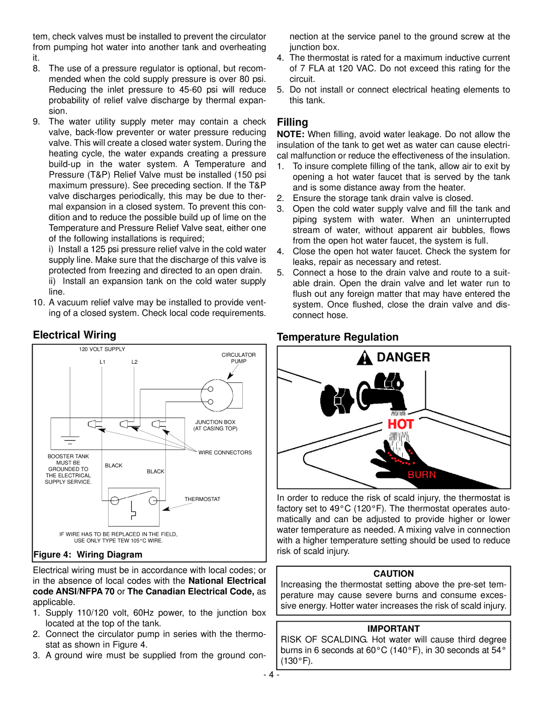
In order to reduce the risk of scald injury, the thermostat is


THERMOSTAT


factory set to 49°C (120°F). The thermostat operates auto-


matically and can be adjusted to provide higher or lower


water temperature as needed. A mixing valve in connection


IF WIRE HAS TO BE REPLACED IN THE FIELD,


with a higher temperature setting should be used to reduce


USE ONLY TYPE TEW 105°C WIRE.


risk of scald injury.


Figure 4: Wiring Diagram


Electrical wiring must be in accordance with local codes; or


CAUTION

in the absence of local codes with the National Electrical


Increasing the thermostat setting above the pre-set tem-

code ANSI/NFPA 70 or The Canadian Electrical Code, as


perature may cause severe burns and consume exces-

applicable.


sive energy. Hotter water increases the risk of scald injury.

1. Supply 110/120 volt, 60Hz power, to the junction box


located at the top of the tank.


IMPORTANT

2. Connect the circulator pump in series with the thermo-


RISK OF SCALDING. Hot water will cause third degree


stat as shown in Figure 4.


burns in 6 seconds at 60°C (140°F), in 30 seconds at 54°

3. A ground wire must be supplied from the ground con-


(130°F).


- 4


-

Page 4
Image 4
GSW WATER HEATING operating instructions Filling, Electrical Wiring, Temperature Regulation, Wiring Diagram, Danger