GSW WATER HEATING Iv Operation, Temperature Adjustment, Draining and Flushing, V Maintenance

Models: WATER HEATING

1 7
Download 7 pages 46.43 Kb
Page 5
Image 5
IV) OPERATION

IV) OPERATION

immediately. If it fails to reset completely and continues to

1.

Follow boiler or heat source installation and operating

release water, the valve is not functioning properly and must


instructions.

be replaced immediately. Close the cold water supply valve,

2.

Fill the tank (see “FILLING” section).

drain the tank as directed in the “Draining and Flushing”

3.

The boiler or water heating source should be set to pro-

section, and replace the T&P valve with a new one. Failure


vide at least 11°C (20°F) higher water temperature than

to install and maintain an approved T&P valve will release


the temperature setting of the storage tank

the manufacturer from any claim that might result from

4.

Turn power on, check for proper operation of boiler and

excessive temperature or pressure. In systems where the


storage tank.

relief valve discharges periodically, this may be due to ther-


mal expansion or to a thermostat that is operating at too

Temperature Adjustment

high a temperature. If you suspect a malfunctioning thermo-

The setting of 49°C (120°F) has been proven to be satis-

stat, contact a qualified service technician for repairs.


factory from the standpoint of operational costs and safety.

Draining and Flushing

We recommend the thermostats remain set at 49°C

(120°F).

Some service work to be performed on the tank requires the


tank to be drained. It is also recommended that the tank be

If water temperature adjustment is required:

drained and flushed every 6 months to remove any sedi-

1.

Turn "OFF" the electrical supply to the tank.

ment and lime which may build up in the bottom of the tank

2.

Remove lower access door.

during operation. Such buildup can result in noisy operation.

3.

Turn back insulation.

To drain the tank:

4.

Adjust thermostat to water temperature desired.

1. Turn "OFF" the electrical supply to the tank.

5.

Replace insulation and access door.

2. Close the cold water supply valve.

6.

Turn "ON" the electrical supply to the tank.

3. Open a nearby hot water faucet served by the system.


4. Connect a hose to the drain valve and route it to an ade-

V) MAINTENANCE

quate drain.

T&P Valve Check

CAUTION! The water being drained can be extremely

hot! The drain hose should be rated for at least 93°C


CAUTION

(200°F). If the drain hose does not have this rating, open the

The out-flowing water is hot. Avoid splashing the water on

cold water supply valve and a nearby hot water faucet

yourself or on the surroundings where it may cause dam-

served by the system until the water flow is no longer hot.

age.

Close the cold water supply valve and resume.


5. Open the drain valve and allow all the water to drain

Do not attempt to operate this storage tank with the cold

from the tank.

water inlet valve closed. The Temperature and Pressure

6. Open the cold water supply valve and flush the tank as

Relief Valve must be manually operated at least once a

needed to remove sediment and any other foreign mat-

year. This involves opening the valve to check that it is flow-

ter that may have entered the system. Close the cold

ing freely and that there are no blockages. WARNING!

water supply valve when clean water flows.

WATER MAY BE HOT and water flow can be forceful.

7. Perform any other servicing as required.

Caution should be taken to ensure that:

8. Close the drain valve, disconnect hose and refill the

1.

No one is in front of or around the outlet of the T&P

tank (see “FILLING” section).


valve discharge line.


9. Turn "ON" the electrical supply to the tank.

2. The water manually discharged will not cause any bod-


ily injury or property damage. The water may be

Cathodic Protection


extremely hot.

Your storage booster tank has been equipped with one or

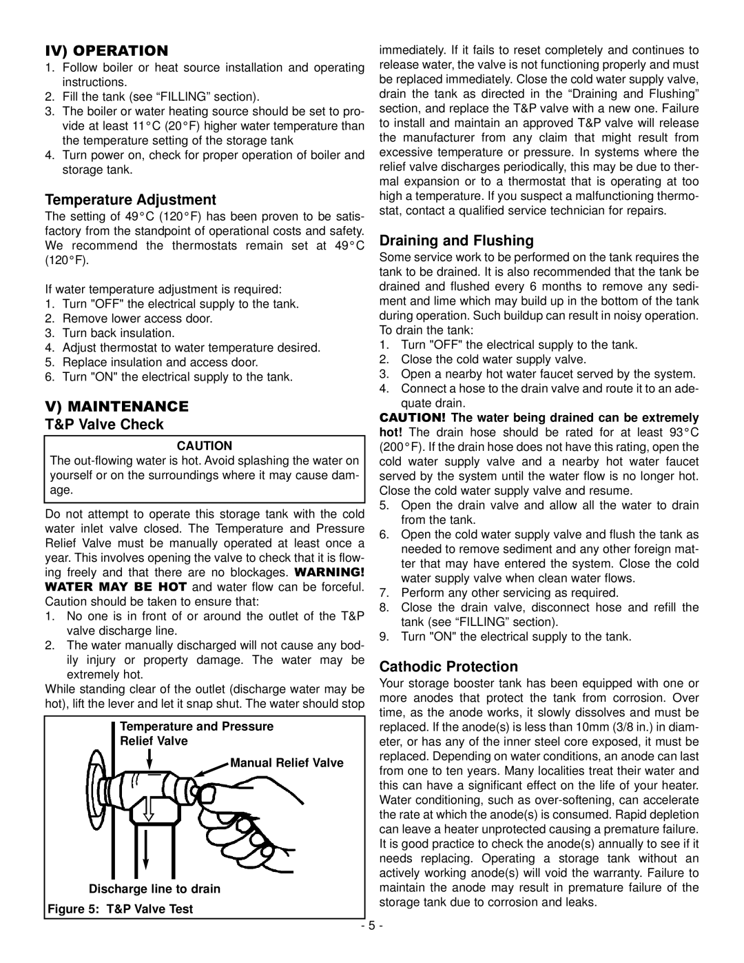
While standing clear of the outlet (discharge water may be

more anodes that protect the tank from corrosion. Over

hot), lift the lever and let it snap shut. The water should stop

time, as the anode works, it slowly dissolves and must be


replaced. If the anode(s) is less than 10mm (3/8 in.) in diam-


Temperature and Pressure


Relief Valve


eter, or has any of the inner steel core exposed, it must be


replaced. Depending on water conditions, an anode can last


Manual Relief Valve


from one to ten years. Many localities treat their water and


this can have a significant effect on the life of your heater.


Water conditioning, such as over-softening, can accelerate


the rate at which the anode(s) is consumed. Rapid depletion


can leave a heater unprotected causing a premature failure.


It is good practice to check the anode(s) annually to see if it


needs replacing. Operating a storage tank without an


actively working anode(s) will void the warranty. Failure to


maintain the anode may result in premature failure of the


Discharge line to drain

Figure 5: T&P Valve Test

storage tank due to corrosion and leaks.


5 -


-

Page 5
Image 5
GSW WATER HEATING Iv Operation, Temperature Adjustment, Draining and Flushing, V Maintenance, Cathodic Protection