Section 1 - General Information
Guardian
1.1GENERATOR
This equipment is a
These models are available. They are rated as follows:
Models 0047210 and 0047220: Provides 15,000 watts (15 kW) of single phase power.
Models 0047230 and 0047240: Provides 20,000 watts (20 kW) of single phase power.
Models 0047250, 0047251, 0047252, 0047253, and 0047260: Provides 25,000 watts (25 kW) of sin- gle phase power.
If this generator is used to power electrical
!load circuits normally powered by a utility power source, it is required by code to install a transfer switch. The transfer switch must effectively isolate the electric system from the utility distribution system when the generator is operating (NEC 701). Failure to isolate an electrical system by such means results in damage to the generator and may also result in injury or even death to utility power work- ers due to backfeed of electrical energy.
1.3AUTOMATIC SYSTEM OPERATION
When this generator, along with its transfer switch, has been installed and interconnected, a circuit board in the generator panel constantly monitors utility power source voltage. Should that voltage drop below a pre- set value, and remain at such a low state for a preset amount of time, the generator cranks and starts. After the generator starts, the transfer switch transfers load circuits so the generator can power them.
When utility source voltage has been restored, the switch
Please reference the transfer switch manual for spe- cific information.
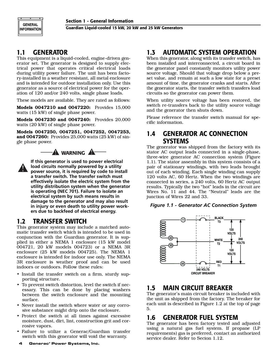
1.4GENERATOR AC CONNECTION
SYSTEMS
The generator was shipped from the factory with its stator AC output leads connected in a
Figure 1.1 - Generator AC Connection System
1.2TRANSFER SWITCH
This generator system may include a matched auto- matic transfer switch which is intended to be used in conjunction with the Guardian generator. It is sup- plied in either a NEMA 1 enclosure (15 kW model 004721, 20 kW models 004723) or a NEMA 3R enclosure (25 kW models 004725). The NEMA 1 enclosure is intended for indoor use only. The NEMA 3R enclosure is weather proof and can be used indoors or outdoors. Follow these rules:
•Install the transfer switch on a firm, sturdy sup- porting structure.
•To prevent switch distortion, level the switch if nec- essary. This can be done by placing washers between the switch enclosure and the mounting surface.
•Never install the switch where water or any corro- sive substance might drip onto the enclosure.
•Protect the switch at all times against excessive moisture, dust, dirt, lint, construction grit and cor- rosive vapors.
•Failure to utilize a Generac/Guardian transfer switch with this generator will void the warranty.
1.5MAIN CIRCUIT BREAKER
The generator’s main circuit breaker is included with the unit as shipped from the factory. The breaker for each unit is described in Figure 1.2 at the top of page 5.
1.6GENERATOR FUEL SYSTEM
The generator has been factory tested and adjusted using a natural gas fuel system. If propane (LP requirements) gas is preferred, contact an authorized service dealer. Refer to Secion 1.12.
4 Generac® Power Systems, Inc.