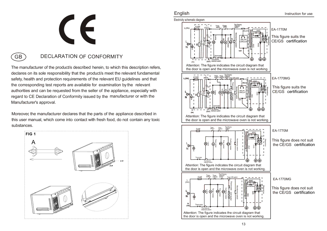
EA-1770MG, EA-1770M specifications
The Haier EA-1770M and EA-1770MG are advanced air conditioning models designed to provide efficient and effective cooling solutions for various spaces. Known for their reliability and modern features, these models embody Haier's commitment to innovation and customer satisfaction.One of the standout features of the EA-1770M and EA-1770MG is their energy efficiency. Both models are equipped with advanced inverter technology, which allows them to adjust their cooling output based on the ambient temperature and user settings. This not only helps in maintaining a consistent indoor climate but also significantly reduces energy consumption, resulting in lower electricity bills.
The design of these air conditioners is both sleek and functional. With a compact form factor, the EA-1770M and EA-1770MG can easily fit into various room sizes without being an eyesore. Their modern aesthetics pair well with contemporary interiors, making them an attractive addition to any space.
In terms of cooling capacity, these models are designed to provide powerful performance. They utilize high-efficiency compressors that deliver rapid cooling, ensuring that spaces reach a comfortable temperature in a short amount of time. Both models are suitable for residential and commercial applications, making them versatile choices for users.
User-friendly features are also a highlight of the Haier EA-1770M and EA-1770MG. The units come with programmable timers and customizable settings, allowing users to set their desired temperatures and cooling schedules. This level of control enhances convenience and improves overall user experience.
In addition, these models are equipped with advanced filtration systems that enhance indoor air quality. The air filters effectively capture dust, allergens, and other airborne particles, ensuring a cleaner environment for occupants. This feature is particularly beneficial for allergy sufferers and families with children.
Furthermore, the Haier EA-1770MG is designed with smart technology integration. Users can control and monitor their air conditioner remotely through a dedicated smartphone app. This connectivity feature adds another layer of convenience, allowing users to adjust settings even when they are not at home.
Overall, the Haier EA-1770M and EA-1770MG represent a blend of performance, efficiency, and modern technology, making them excellent choices for anyone looking to enhance their indoor comfort. With their effective cooling capabilities and user-friendly features, these air conditioners stand out in the competitive HVAC market.

