
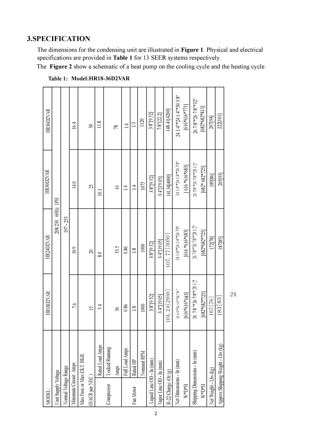
HR24D2VAR, HR36D2VAR, HR18D2VAR, HR30D2VAR specifications
Haier, a globally recognized brand in home appliances, has developed a line of air conditioning units that includes the HR30D2VAR, HR18D2VAR, HR36D2VAR, and HR24D2VAR models. These units are designed to deliver optimal comfort and energy efficiency for both residential and commercial spaces.One of the standout features of these models is their advanced inverter technology. This allows the air conditioners to adjust the compressor speed according to the cooling requirements of the room. As a result, these units can cool spaces rapidly while consuming less energy compared to traditional models. The inverter technology not only contributes to energy savings but also ensures a quieter operation, making them ideal for bedrooms and workspaces.
The HR series models are equipped with multiple cooling modes, allowing users to select the most appropriate setting based on their comfort needs. Whether it's a hot summer day or a mild evening, users can tailor the temperature to their liking. Additionally, the models come with a sleep mode that gradually adjusts the temperature, providing a comfortable sleeping environment while saving energy.
Another significant characteristic of these air conditioners is their energy efficiency ratings. Many of the HR series units boast high SEER (Seasonal Energy Efficiency Ratio) ratings, indicating their effectiveness in cooling while minimizing electricity consumption. This is particularly beneficial for environmentally conscious consumers looking to reduce their carbon footprint.
Furthermore, the HR30D2VAR, HR18D2VAR, HR36D2VAR, and HR24D2VAR models incorporate robust air filtration systems designed to improve indoor air quality. These filters capture dust, pollen, and other allergens, making it an excellent choice for those with respiratory issues or allergies. Regular maintenance is also simplified, as filters can be easily accessed and cleaned or replaced.
Connectivity is another feature that enhances user experience. Many of the Haier air conditioning units in this series come with smart technology compatibility, allowing users to control their air conditioner through their smartphone or smart home systems. This remote control capability enables adjustments even when users are away from home, providing convenience and energy management.
In summary, the Haier HR30D2VAR, HR18D2VAR, HR36D2VAR, and HR24D2VAR air conditioners combine advanced technologies such as inverter operation, high energy efficiency, robust filtration systems, and smart connectivity. These features make them suitable for a variety of settings, ensuring comfort and ease of use for homeowners and businesses alike.