Flush Ceiling Mount
Proceed to step 3.
Note: Plastic cover is not used for flush mount.
Wall Mount
With the addition of the OmniMount
Step 3
Fig. 1
Gently pull the extension tube of the pipe drop as- sembly down to the required projector height. Rotate extension tube so that adjustment screw holes are visible through the support tube. (Fig. 1)
Secure the pipe position by installing ½” long hex screws (I) into adjustment screw holes. For a cleaner appearance, insert plastic plugs (K) into unused holes on extension tube.
Fig. 2
Separate top and bottom projector mounting plates (A&B), by sliding them apart. (Fig. 2)
Thread ¼” hex head set screw (F) into side of pipe collar, on top projector mounting plate (A). (Fig. 3)
Fig. 3
Note: If necessary, screw in tilt knob to gain access to the set screw hole.
4
Loosely thread top projector mounting plate (A) onto threaded portion of pipe drop.
Fig. 4
Position top projector mounting plate into desired orientation (horizontal or vertical), and then tighten set screw (F). (Fig. 4)
Thread cable bundle through cable management port at top of pipe assembly, down through the pipe assembly, and then out through the cable management port on the rear of the projector Fig. 5 mounting plate. (Fig. 5) (Standard ceiling mount only) Be sure
to leave enough cable to reach the mounted projector.
Flush Ceiling Mount
For flush ceiling mount, loosely thread top projector mounting plate directly onto threaded portion of ceiling plate.
Step 4
Determine required mounting screw size (4, 5 or 6 mm) for projector.
Note: Consult projectors owners’ manual for screw sizes and mounting holes.
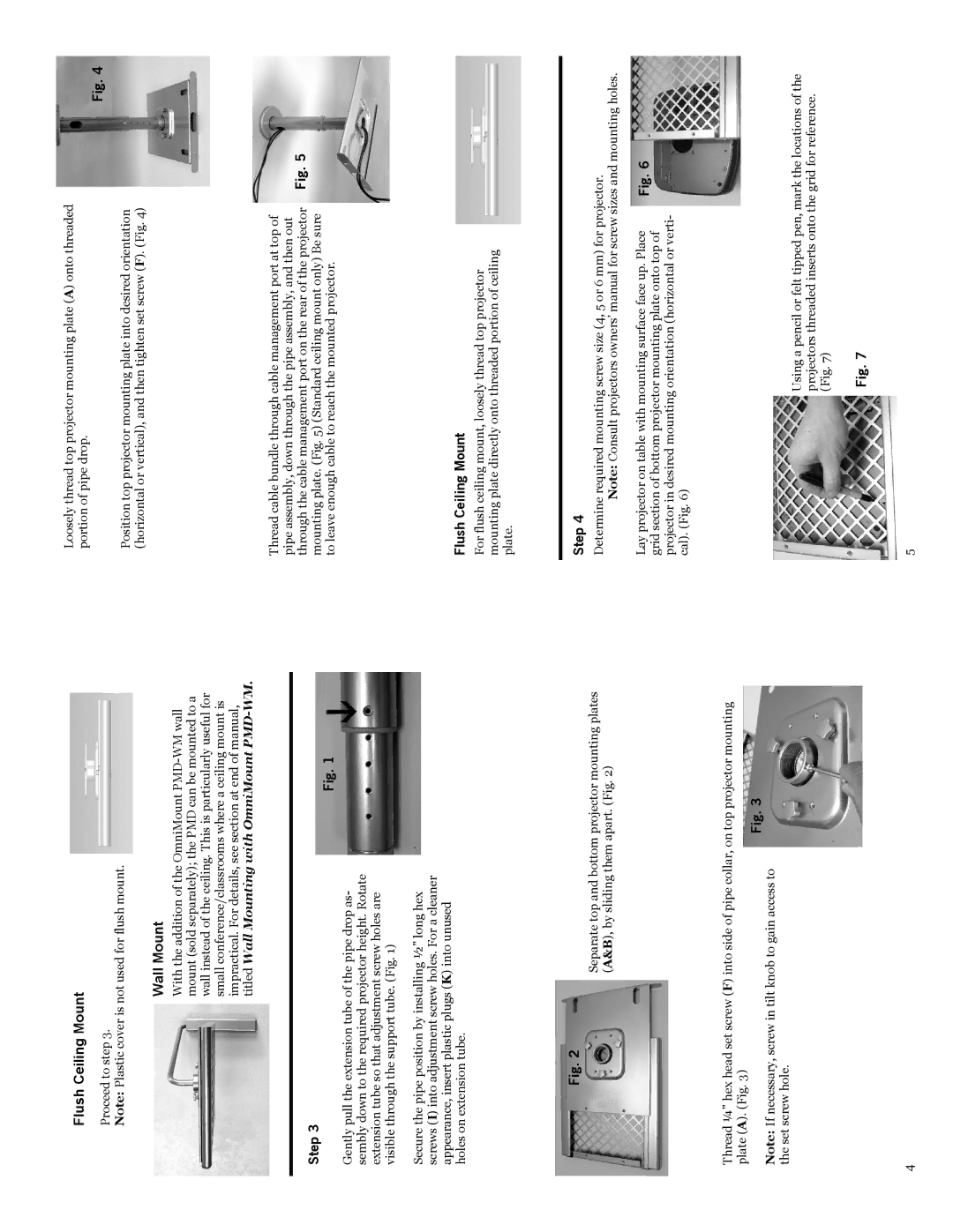
Lay projector on table with mounting surface face up. Place | Fig. 6 |
grid section of bottom projector mounting plate onto top of |
|
projector in desired mounting orientation (horizontal or verti- |
|
cal). (Fig. 6) |
|
Using a pencil or felt tipped pen, mark the locations of the projectors threaded inserts onto the grid for reference. (Fig. 7)
Fig. 7
5