Place a large washer (1) over mounting screw, and then in- sert screw through grid at marked location. (Fig. 8)
Fig. 8
Lift the projector mounting plate and place a second large washer (1) onto the end of the screw, followed by a metal spacer (2). Loosely thread
Fig. 9
Repeat this procedure for the remaining threaded inserts. (Fig. 10)
Note: A 1” plastic spacer (3) is included for projectors with uneven mounting surfaces. Trim the plastic spacer to the required length, and install on appropriate mounting screw.
Fig. 10
Once all mounting screws have been installed, square up the projector mounting plate, and then tighten the mounting screws securely.
Caution: Do not force or over tighten the mounting screws, or damage to the projector may occur.
Step 5
Slide the bottom projector mounting plate onto | Fig. 11 |
the previously installed top projector mounting |
|
plate. (Fig. 11) |
|
Note: Make sure that the cables don’t get |
|
pinched while sliding the plates together. |
|
6
Part | Projector Mounting Hard- | Qty. | Bag |
| ||
| ware |
|
|
|
| |
|
|
|
|
|
| |
1 | Large Washer |
| 8 | (a) |
| |
|
|
|
|
|
| |
2 | Metal Spacer: 3/8” |
| 4 | (a) |
| |
|
|
|
|
| Hardware Bags | |
3 | Plastic Spacer: 1” |
| 1 | (b) | ||
|
|
|
|
|
|
|
|
|
|
|
| ||
|
|
|
|
|
|
|
4 | Screw: |
| Screw: | 4 | (c) |
|
| 5mm x 25mm |
| 6mm x 25mm |
|
|
|
|
|
|
|
|
|
|
5 | Screw: |
| Screw: | 4 | (c) |
|
| 4mm x 25mm |
| 5mm x 25mm |
|
|
|
|
|
|
|
|
|
|
6 | Screw: |
| Screw: | 4 | (c) |
|
| 3mm x 25mm |
| 4mm x 25mm |
|
|
|
|
|
|
|
|
|
|
|
|
|
|
|
|
|
Step 1
With an electronic stud finder, locate center of ceiling stud in desired mounting loca- tion. Unscrew ceiling plate (E) from Projector Mounting top plate (A). Use ceiling plate as a template, and mark mounting hole locations. Drill mounting holes to a depth of 3” using a 3/16” drill bit. Mount ceiling plate to stud with 5/16” lag bolts (J).
Step 2
Determine type of installation:
•Standard Ceiling Mount
•Extended Ceiling Mount
•Flush Mount
•Wall Mount
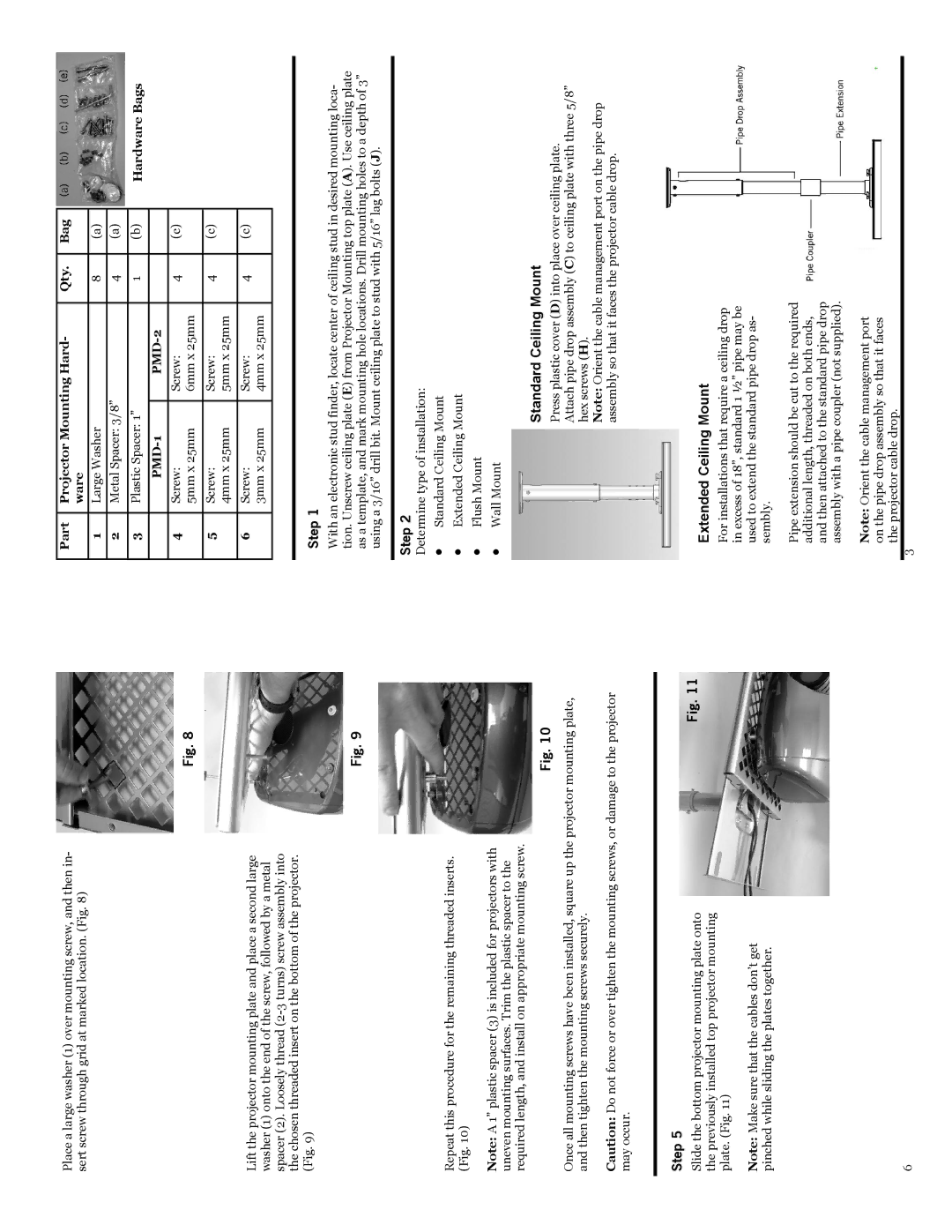
Standard Ceiling Mount
Press plastic cover (D) into place over ceiling plate.
Attach pipe drop assembly (C) to ceiling plate with three 5/8” hex screws (H).
Note: Orient the cable management port on the pipe drop assembly so that it faces the projector cable drop.
Extended Ceiling Mount
For installations that require a ceiling drop in excess of 18”, standard 1 ½” pipe may be used to extend the standard pipe drop as- sembly.
Pipe extension should be cut to the required additional length, threaded on both ends, and then attached to the standard pipe drop assembly with a pipe coupler (not supplied).
Note: Orient the cable management port on the pipe drop assembly so that it faces the projector cable drop.
3