Halfords hi 3 bike instructions 6/8/07 12:05 PM Page 3
INITIAL PREPARATION | CARRIER |
1 | 3 | Adjuster Plate |
|
|
2
REFER TO
APPLICATION
GUIDE
1
3 180°
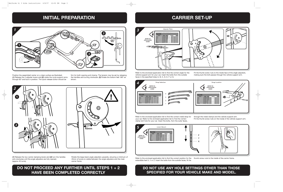
Position the assembled carrier on a clean surface as illustrated. | firm for both opening and closing. The tension may be set by releasing |
(1) Release the 2 adjuster levers and (2) rotate the cycle support arms | the handles and turning clockwise. (3) Rotate the bottom feet 180º as |
through 90º and lock in position. The quick release action should be | shown. |
2
1
2
45mm
(1) Release the two carrier clamping levers and (2) turn the handles | Rotate the large black angle adjusters upwards, ensuring a minimum of |
45mm of screw is visible between the angle adjusters and the main | |
(approx 40 turns). | carrier frame. |
Refer to the enclosed application list to find the correct angle for the | Fit the thumb screw nuts to the inside face of the angle adjusters, | |||||||||
vehicle support arm for your car. Insert the bolts from the outside | making sure the bolt passes through the vehicle support arm. | |||||||||
faces in the specified holes A, B, C, D, E, F or G. |
|
|
|
| ||||||
4 | Strap Selection |
|
| Strap Location | ||||||
REFER TO |
|
| REFER TO | |||||||
|
|
|
|
| ||||||
|
|
| APPLICATION |
|
| APPLICATION | ||||
|
|
| GUIDE |
|
|
|
| GUIDE | ||
|
|
|
|
|
| |||||
|
|
|
|
|
|
|
|
|
|
|
|
|
|
|
|
|
|
|
|
|
|
|
|
|
|
|
|
|
|
|
|
|
|
|
|
|
|
|
|
|
|
|
|
Refer to the enclosed application list to find the correct metal strap for | through the metal clamps and the vehicle support arm. |
your car. Refer to the enclosed application list to find the correct | Fit the thumb screw nuts on the inside of the vehicle support arm. |
clamp bolt hole for your car. Insert the bolts, from the outer faces, |
|
5 | Lower Mount |
| |
REFER TO |
|
APPLICATION |
|
GUIDE |
|
Refer to the enclosed application list to find the correct position for the thumb screw nuts to the inside of the carrier frame. extendible feet X, Y or Z. Insert the bolts from the outside faces, fit the
DO NOT PROCEED ANY FURTHER UNTIL STEPS 1 + 2
HAVE BEEN COMPLETED CORRECTLY
DO NOT USE ANY HOLE SETTINGS OTHER THAN THOSE SPECIFIED FOR YOUR VEHICLE MAKE AND MODEL.
