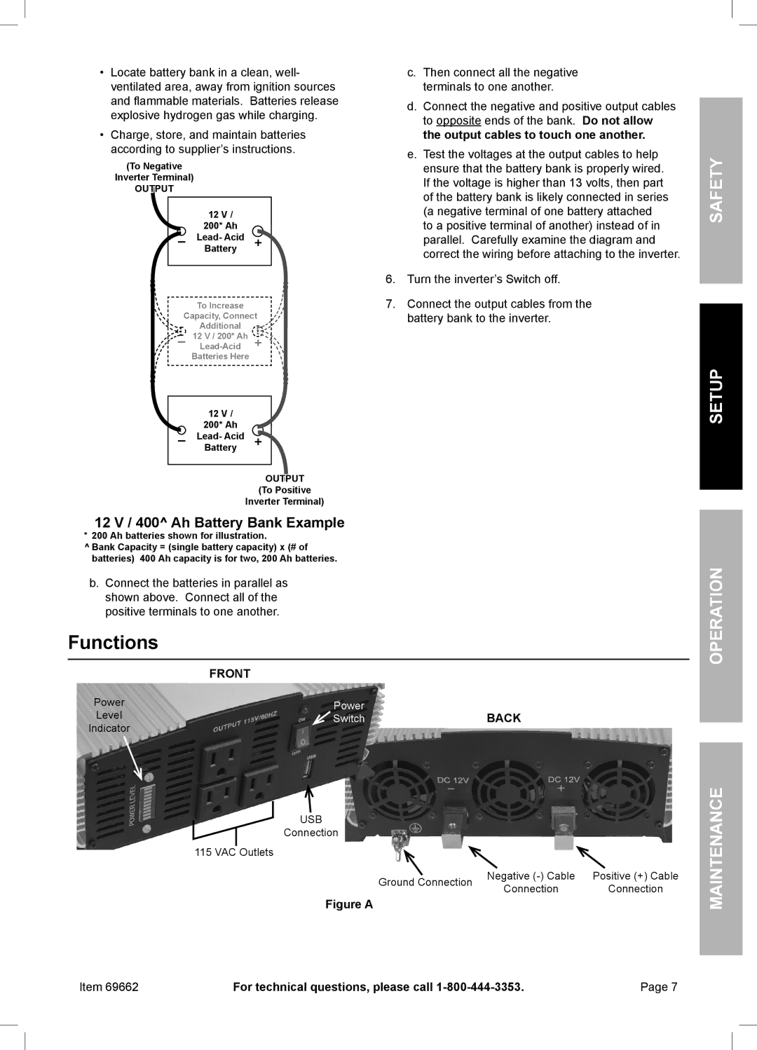
•Locate battery bank in a clean, well- ventilated area, away from ignition sources and flammable materials. Batteries release explosive hydrogen gas while charging.
•Charge, store, and maintain batteries according to supplier’s instructions.
(To Negative
Inverter Terminal)
OUTPUT
12 V /
200* Ah
–Lead- Acid + Battery
To Increase
Capacity, Connect
Additional
![]() – 12 V / 200* Ah
– 12 V / 200* Ah ![]() +
+![]()
Batteries Here
12 V /
200* Ah
–Lead- Acid + Battery
OUTPUT
(To Positive
Inverter Terminal)
c.Then connect all the negative terminals to one another.
d.Connect the negative and positive output cables to opposite ends of the bank. Do not allow the output cables to touch one another.
e.Test the voltages at the output cables to help ensure that the battery bank is properly wired. If the voltage is higher than 13 volts, then part of the battery bank is likely connected in series (a negative terminal of one battery attached to a positive terminal of another) instead of in parallel. Carefully examine the diagram and correct the wiring before attaching to the inverter.
6.Turn the inverter’s Switch off.
7.Connect the output cables from the battery bank to the inverter.
Safety
Setup
12 V / 400^ Ah Battery Bank Example
* 200 Ah batteries shown for illustration.
^Bank Capacity = (single battery capacity) x (# of batteries) 400 Ah capacity is for two, 200 Ah batteries.
b.Connect the batteries in parallel as shown above. Connect all of the positive terminals to one another.
Functions
FRONT
Power | Power | BACK |
Level | Switch | |
Indicator |
|
|
USB
Connection
115 VAC Outlets
Ground Connection | Negative | Positive (+) Cable | |
Connection | Connection | ||
|
Figure A
Item 69662 | For technical questions, please call | Page 7 |
