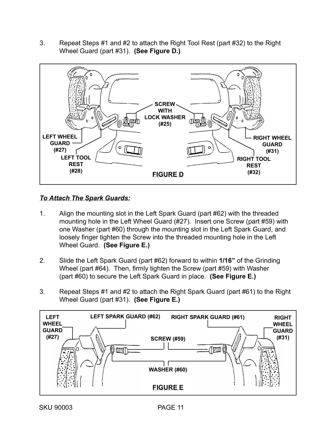
3.Repeat Steps #1 and #2 to attach the Right Tool Rest (part #32) to the Right Wheel Guard (part #31). (See Figure D.)
SCREW
WITH
LOCK WASHER
(#25)
LEFT WHEEL
GUARD
(#27)
LEFT TOOL
REST (#28)
| RIGHT WHEEL |
| GUARD |
| (#31) |
| RIGHT TOOL |
| REST |
FIGURE D | (#32) |
|
To Attach The Spark Guards:
1.Align the mounting slot in the Left Spark Guard (part #62) with the threaded mounting hole in the Left Wheel Guard (#27). Insert one Screw (part #59) with one Washer (part #60) through the mounting slot in the Left Spark Guard, and loosely finger tighten the Screw into the threaded mounting hole in the Left Wheel Guard. (See Figure E.)
2.Slide the Left Spark Guard (part #62) forward to within 1/16” of the Grinding Wheel (part #64). Then, firmly tighten the Screw (part #59) with Washer (part #60) to secure the Left Spark Guard in place. (See Figure E.)
3.Repeat Steps #1 and #2 to attach the Right Spark Guard (part #61) to the Right Wheel Guard (part #31). (See Figure E.)
LEFT | LEFT SPARK | GUARD (#62) RIGHT SPARK GUARD (#61) |
|
| RIGHT | |||||||||
WHEEL |
|
|
|
|
|
|
|
|
|
|
| WHEEL | ||
|
|
|
|
|
|
|
|
|
|
|
|
|
|
|
GUARD |
|
|
|
|
|
|
|
|
|
|
| GUARD | ||
(#27) |
|
|
|
|
| SCREW (#59) |
| (#31) | ||||||
|
|
|
|
| ||||||||||
|
|
|
|
|
| |||||||||
|
|
|
|
|
|
|
|
|
|
|
|
|
|
|
|
|
|
|
|
|
|
|
|
|
|
|
|
|
|
|
|
|
|
|
|
|
|
|
|
|
|
|
|
|
|
|
|
|
|
|
|
|
|
|
|
|
|
|
|
|
|
|
|
|
|
|
|
|
|
|
|
|
|
|
WASHER (#60)
FIGURE E
SKU 90003 | PAGE 11 |
