94873 specifications
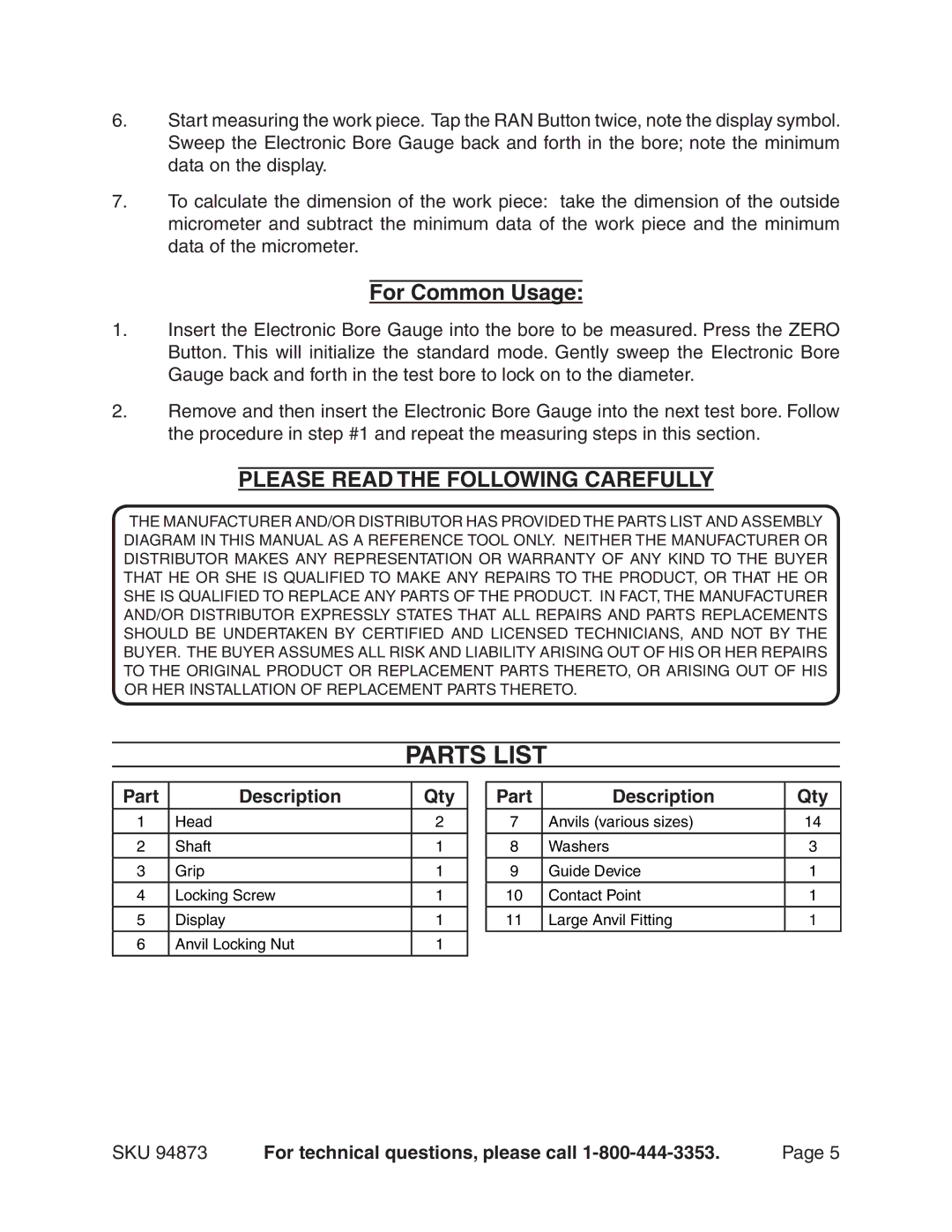
Harbor Freight Tools 94873 is a versatile addition to any workshop, designed for both professional tradespeople and DIY enthusiasts. This product exemplifies the brand's commitment to delivering quality tools at budget-friendly prices.One of the standout features of the Harbor Freight Tools 94873 is its robust construction. Built with high-grade materials, it ensures durability and longevity, capable of withstanding the demands of regular use in various environments. This tool is perfect for heavy-duty tasks, making it a reliable choice for those who require strength and resilience in their equipment.
The 94873 model comes equipped with a powerful motor that provides exceptional performance. This motor is designed to deliver consistent torque, making it ideal for a wide range of applications, from automotive repair to home improvement projects. Users appreciate the efficiency offered by this tool, as it allows them to complete tasks quicker and with greater ease.
Another noteworthy characteristic of the Harbor Freight Tools 94873 is its user-friendly design. The ergonomic handle ensures comfort during extended use, helping to reduce fatigue. This feature is particularly important for professionals who may spend long hours working with the tool, as well as for DIY users who want to maintain a comfortable grip while tackling their projects.
In terms of technology, the 94873 incorporates advanced engineering that enhances its overall functionality. The tool is designed for easy maintenance, which means users can keep it in optimal condition without extensive effort. This results in prolonged life and better reliability over time.
Portability is another key aspect of the Harbor Freight Tools 94873. It is lightweight, making it easy to transport to different job sites or store when not in use. This factor is crucial for those who need to move their tools frequently, as it simplifies workflow and increases productivity.
Overall, the Harbor Freight Tools 94873 is a commendable tool that blends durability, performance, and user-oriented features. Its competitive pricing further cements its position as a go-to choice for those seeking a dependable tool that does not compromise on quality. Whether you're a seasoned professional or a hobbyist, the 94873 can undoubtedly enhance your toolkit, making it an essential investment for any user dedicated to achieving excellent results in their projects.

