4.Depress the Spindle Lock (39) to hold the Spindle stationary. (See Figure F.)
5.Use the accessory Hex Wrench (69) to unscrew and remove the Screw (48).
(See Figure F.)
6.Remove the Outer Plate (18). (See Figure F.)
7.Raise up on the Safety Cover (26). Then, install the Saw Blade (20) on the Spindle of the tool. (See Figure F.)
8.Release the Safety Cover (18), and allow it to return to its original position.
(See Figure F.)
9.
To Adjust The Depth Of Cut:
1.The depth of cut may be adusted to a maximum of
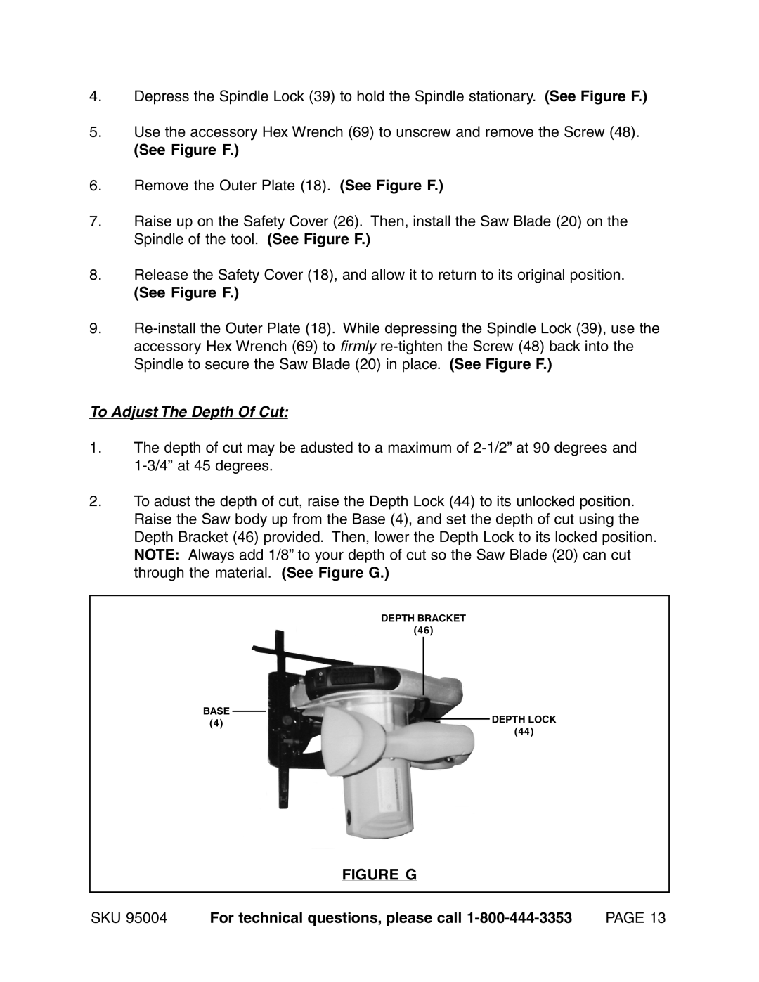
2.To adust the depth of cut, raise the Depth Lock (44) to its unlocked position. Raise the Saw body up from the Base (4), and set the depth of cut using the Depth Bracket (46) provided. Then, lower the Depth Lock to its locked position. NOTE: Always add 1/8” to your depth of cut so the Saw Blade (20) can cut through the material. (See Figure G.)
DEPTH BRACKET
(46)
BASE
(4)DEPTH LOCK
(44)
FIGURE G
SKU 95004 | For technical questions, please call | PAGE 13 |
