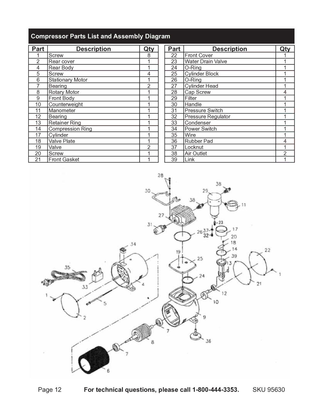
Compressor Parts List and Assembly Diagram
Part Description
1Screw
2Rear cover
4Rear Body
5Screw
6Stationary Motor
7Bearing
8Rotary Motor
9Front Body
10 Counterweight
11 Manometer
12 Bearing
13 Retainer Ring
14 Compression Ring
17 Cylinder
18 Valve Plate
19 Valve
20 Screw
21 Front Gasket
Qty
8
1
1
4
1
2
1
1
1
1
1
1
1
1
1
2
1
1
Part Description
22Front Cover
23Water Drain Valve
24
25Cylinder Block
26
27Cylinder Head
28Cap Screw
29Filter
30Handle
31Pressure Switch
32Pressure Regulator
33Condenser
34Power Switch
35Wire
36Rubber Pad
37Locknut
38Air Outlet
39Link
Qty
1
1
1
1
1
1
4
1
1
1
1
1
1
1
4
1
2
1
Page 12 | For technical questions, please call | SKU 95630 |
