Manuals
/
Harman-Kardon
/
Home Audio
/
Stereo Receiver
Harman-Kardon
AVR 630 Speaker Selection, Speaker Placement, Installation and Connections
Models:
AVR 630
1
19
54
54
Download
54 pages
46.44 Kb
16
17
18
19
20
21
22
23
Troubleshooting
Specs
Install
Surround Mode Chart
Note for RGB signal with SCART
Power Indicator
System Configuration
Recalling Preset Stations
Audio Setup
Learning Commands
Page 19
Image 19
Page 18
Page 20
Page 19
Image 19
Page 18
Page 20
Contents
AVR 630 Audio/ Video Receiver
2, route de Tours 72500 Château-du-Loir FRANCE
Table of Contents
Declaration of Conformity
We, Harman Consumer International
On-screenmenu and display system
Description and Features
Introduction
Multiple digital inputs and outputs
Handle the AC Power Cord Gently
Introduction / Safety Information
Important Safety Information
4INTRODUCTION / SAFETY INFORMATION
Tuning Selector
1 Main Power Switch
2 System Power Control
3 Power Indicator
6FRONT PANEL CONTROLS
Coaxial Ó
33 for more information
Front Panel Controls
Digital Audio Outputs Connect these
Rear Panel Connections
Rear Panel Connections
Unswitched Outlet
Switched Outlet
AC Power Cord Jack Connect the AC
REAR PANEL CONNECTIONS
AVR 630 when appropriate upgrades are available
+ and negative -terminals
Rear Panel Connections
1 0
Main Remote Control Functions
H I D C E G F P P P
GDigital Select Press this button to assign
Main Remote Control Functions
MAIN REMOTE CONTROL FUNCTIONS
8-ChannelDirect Inputs the input
Main Remote Control Functions
12MAIN REMOTE CONTROL FUNCTIONS
DTS Neo 6 MUSIC DTS Neo 6 MOVIES
MAIN REMOTE CONTROL FUNCTIONS
Main Remote Control Functions
14ZONE II REMOTE CONTROL FUNCTIONS
Zone II Remote Control Functions
Video Equipment Connections
Installation and Connections
INSTALLATION AND CONNECTIONS
Audio Equipment Connections
Video Audio Inputs
Important Notes for S-Videoconnections
16INSTALLATION AND CONNECTIONS
SCART A/V Connections
Installation and Connections
Note for RGB signal with SCART
If you use a unit providing RGB signals on a
Important Note for the Use of SCART-CinchAdapters
AC Power Connections
System and Power Connections
Main Room Remote Control Extension
RS-232Connections
Installation and Connections
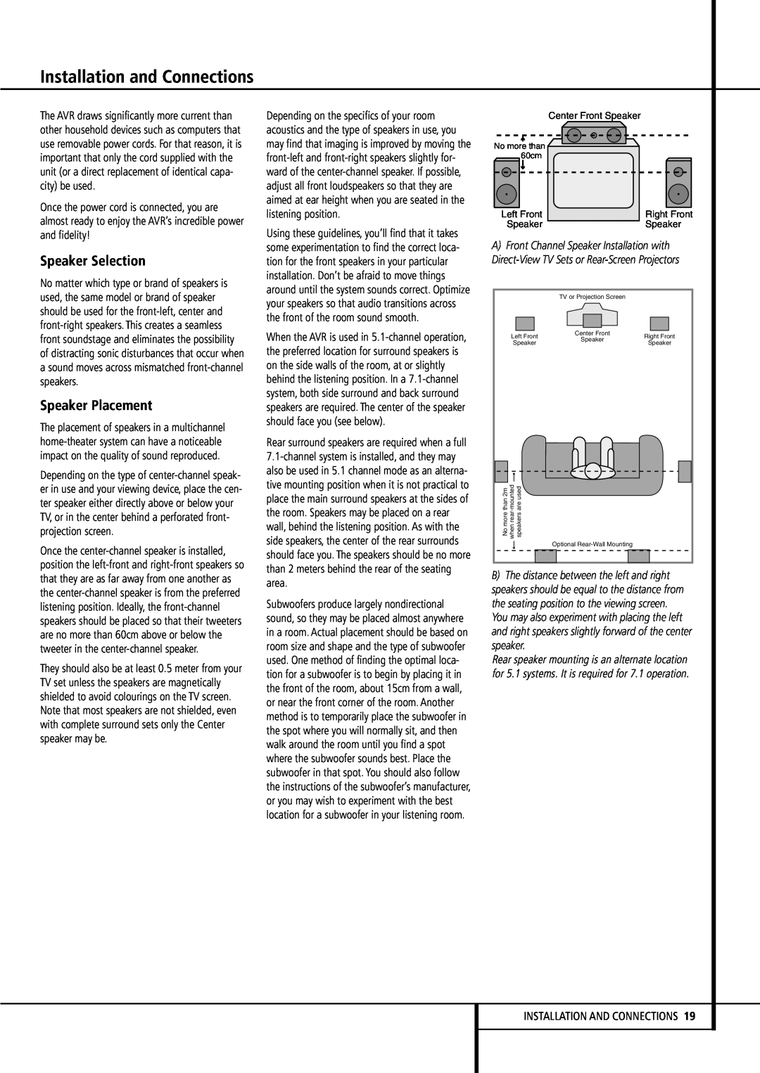
Speaker Placement
Speaker Selection
BThe distance between the left and right
Input Setup
System Configuration
Using the On-ScreenDisplay
System Setup
System Configuration
SYSTEM CONFIGURATION
Component Video Inputs may be
Set Button F
Fto bring up the SPEAKER SETUP menu Figure
Audio Setup
22SYSTEM CONFIGURATION
Speaker Setup
SYSTEM CONFIGURATION
System Configuration
System Configuration
Surround Setup
System Configuration
Adjustments for Other Inputs
Button Eso that SURROUND
presss the Set Button F
individually for each input in use
Delay Settings
Night Mode Settings
26SYSTEM CONFIGURATION
3.Press and hold the SPL Select Button
setting, then press Set Fto confirm the set- ting
Output Level Adjustment
Using EzSet
press the Clear Button
28SYSTEM CONFIGURATION
Eon the remote
1.Press and hold the SPL Select Button
MODE
Surround Mode Chart
FEATURES
Operation
MODE
Surround Mode Chart
FEATURES
Operation
Basic Operation
Switched AC Outlets and the Power
Using the Sleep Timer
8-ChannelDirect Inputs and when the
Surround Mode Selection
Controls and Use of Headphones
Volume Up/Down
One of the most important features of the
or front panel *Ó
Digital Audio Playback
Dolby Digital
rear panel
Selecting a Digital Source
Digital Bitstream Indicators
Speaker/Channel Indicators
2.0audio, while the main feature is available in
puts for Tape Outputs
Tape Recording
Front Panel In/Outputs
Night Mode
Operation
Output Level Adjustment With Source Signals
Memory Backup
Dim Function
Surround Amplifier Channel Assignment
Advanced Features
Turn On Volume Level
ADVANCED FEATURES
Installation
Advanced Features / Multiroom Operation
Semi-OSDSettings
Full-OSDTime Out Adjustment
Multiroom Operation
Multiroom Setup
location volume
frequency Kè, change the tuner preset
Basic Tuner Operation
Preset Tuning
Recalling Preset Stations
Multiroom Operation / Tuner Operation
RDS Display Options
RDS Tuning
Tuner Operation
RDS Operation
Fappears
Configuring the Remote
Programming the Remote
Preprogrammed Code Entry
PROGRAMMING THE REMOTE
Learning Commands
Programming the Remote
Automatic Code Entry
44PROGRAMMING THE REMOTE
Changing Devices
Programming the Remote
PROGRAMMING THE REMOTE
Macro Programming
Recording a Macro
Programming the Remote
Erasing a Macro
Punch-ThroughConfiguration
Power On VID 2/TV Power On VID 3/Cable
Power On AVR Logic 7 O
red. Press the ⁄¤ Navigation Buttons
Volume Punch-Through
Note for Volume Punch-Through
Channel Punch-Through
4. Within five seconds, press the Set Button
EzSet Configuration
Transport Punch-Through
⁄¤ Navigation Buttons Eonce so that
‹/› Navigation Buttons Eas required
Renaming
Renaming a Device
Notes on Renaming Devices
Notes on Renaming Keys
Resetting the Remote
Figure Figure
11.At this point you have two options
A V R L O W B A T T E R Y
Programming the Remote
PROGRAMMING THE REMOTE
T I M E O U T O R C L R K E Y P R E S S E D
SOLUTION
Troubleshooting Guide
Processor Reset
SYMPTOM
AM Tuner Section
Technical Specifications
Audio Section
FM Tuner Section
Part No. ZKD0201HA00-4
Harman Consumer International
Top
Page
Image
Contents