Parts and components − front panel
A 
![]() D
D
| E | |
| F | |
B | G | |
C | H | |
I | ||
|
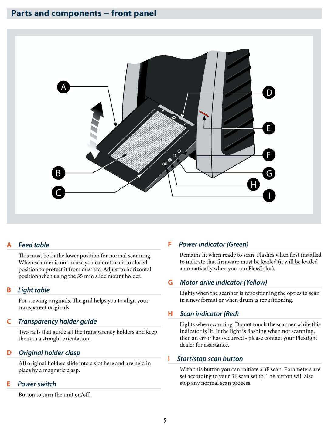
A Feed table
This must be in the lower position for normal scanning. When scanner is not in use you can return it to closed position to protect it from dust etc. Adjust to horizontal position when using the 35 mm slide mount holder.
B Light table
For viewing originals. The grid helps you to align your transparent originals.
C Transparency holder guide
Two rails that guide all the transparency holders and keep them in a straight orientation.
D Original holder clasp
All original holders slide into a slot here and are held in place by a magnetic clasp.
E Power switch
Button to turn the unit on/off.
F Power indicator (Green)
Remains lit when ready to scan. Flashes when first installed to indicate that firmware must be loaded (it will be loaded automatically when you run FlexColor).
G Motor drive indicator (Yellow)
Lights when the scanner is repositioning the optics to scan in a new format or when drum is repositioning.
H Scan indicator (Red)
Lights when scanning. Do not touch the scanner while this indicator is lit. If the light is flashing when not scanning, then an error has occurred - please contact your Flextight dealer for assistance.
I Start/stop scan button
With this button you can initiate a 3F scan. Parameters are set according to your 3F scan setup. The button will also stop any normal scan process.
5
