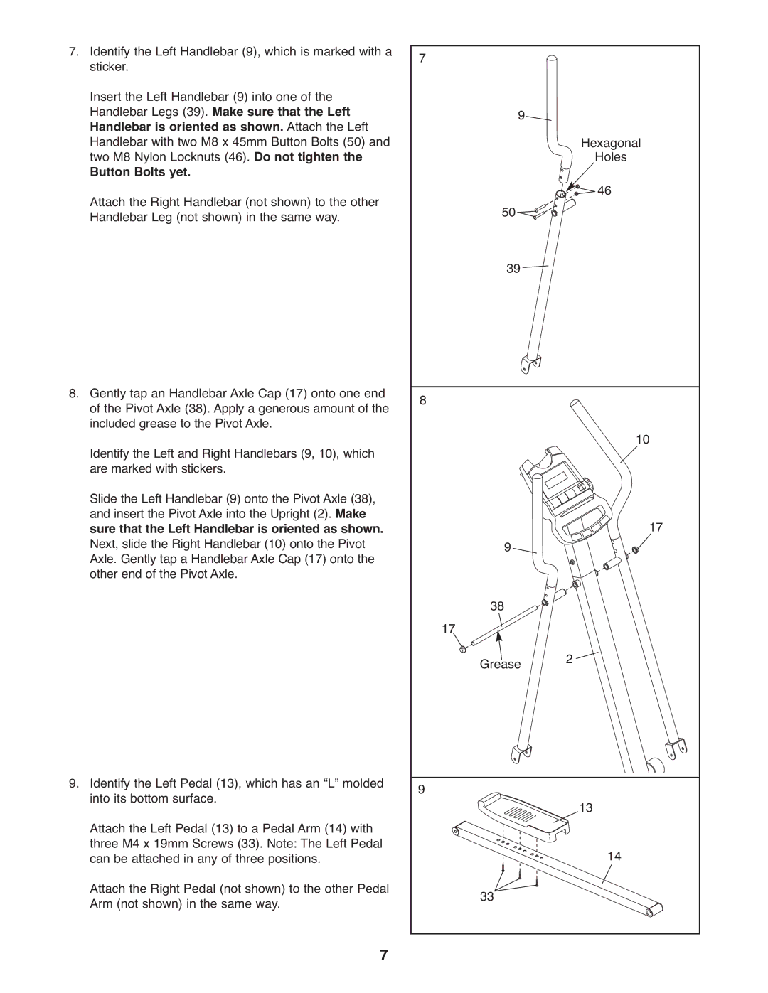
7.Identify the Left Handlebar (9), which is marked with a sticker.
Insert the Left Handlebar (9) into one of the Handlebar Legs (39). Make sure that the Left Handlebar is oriented as shown. Attach the Left Handlebar with two M8 x 45mm Button Bolts (50) and two M8 Nylon Locknuts (46). Do not tighten the
Button Bolts yet.
Attach the Right Handlebar (not shown) to the other Handlebar Leg (not shown) in the same way.
8.Gently tap an Handlebar Axle Cap (17) onto one end of the Pivot Axle (38). Apply a generous amount of the included grease to the Pivot Axle.
Identify the Left and Right Handlebars (9, 10), which are marked with stickers.
Slide the Left Handlebar (9) onto the Pivot Axle (38), and insert the Pivot Axle into the Upright (2). Make sure that the Left Handlebar is oriented as shown. Next, slide the Right Handlebar (10) onto the Pivot Axle. Gently tap a Handlebar Axle Cap (17) onto the other end of the Pivot Axle.
9.Identify the Left Pedal (13), which has an “L” molded into its bottom surface.
Attach the Left Pedal (13) to a Pedal Arm (14) with three M4 x 19mm Screws (33). Note: The Left Pedal can be attached in any of three positions.
Attach the Right Pedal (not shown) to the other Pedal Arm (not shown) in the same way.
7
7 |
|
| |
| 9 | Hexagonal | |
|
| ||
|
| Holes | |
| 50 | 46 | |
|
| ||
| 39 |
| |
8 |
|
| |
|
| 10 | |
| 9 | 17 | |
|
| ||
17 | 38 |
| |
Grease | 2 | ||
| |||
9 |
| 13 | |
|
| ||
|
| 14 | |
| 33 |
|
