G R

v

D A H


E


v


L

B


U.S.


B


v


v

B

(3 FT)


v


F

v


v

I

M

v


X


A


J or K

M

N

P

Q

(See Note 2)

V

T

VS Electrical Service

D*

V

S V

V

= VENT TERMINAL

X = AIR SUPPLY INLET

= AREA WHERE TERMINAL IS NOT PERMITTED

A

=

12 inches

clearances above grade, veran-

K

=

3 ft. (U.S.A.)


(See Note 1)

da, porch, deck or balcony


6 ft. (Canada)

clearance to a mechanical

B

=

12 inches

clearances to window or door


(powered) air supply inlet

L**

=

7 ft

clearance above paved side-


that may be opened, or to per-


(See Note 1)


walk or a paved driveway lo-


manently closed window. (Glass)


cated on public property

D*

=

18 inches

vertical clearance to unventilat-

M*** =

18 inches

clearance under veranda, porch,


ed soffit or to ventilated soffit lo-


deck, balcony or overhang


cated above the terminal


42 inches

vinyl


*30 inches

for vinyl clad soffits and below


S

=

6 inches


clearance from sides of


electrical service


(See Note 5)


electrical service

F

=

9 inches

clearance to outside corner


T

=

12 inches


clearance above electrical

G

=

6 inches

clearance to inside corner


(See Note 5)


service

H

=

3 ft. (Canada)

not to be installed above a gas


Alcove Applications


meter/regulator assembly within 3


feet (90cm) horizontally from the


N


=

6 inches


non-vinyl sidewalls


center-line of the regulator


12 inches


vinyl sidewalls


I

=

3 ft. (U.S.A.)


P


=

8 ft.


6 ft. (Canada)

clearance to gas service regula-


QMIN


RMAX


tor vent outlet


J

=

9 inches (U.S.A.)


1 cap


3 feet


2 x Q ACTUAL


12 inches (Canada)clearance to non-mechanical air


2 caps


6 feet


1 x Q ACTUAL


supply inlet to building or the


3 caps


9 feet


2/3 x Q ACTUAL


combustion air inlet to any other


4 caps


12 feet


1/2 x Q ACTUAL


appliance


QMIN = # termination caps x 3 RMAX = (2 / # termination caps) x QACTUAL


**a vent shall not terminate directly above a sidewalk or paved driveway which is located between two single family dwellings and serves both dwellings.

***only permitted if veranda, porch, deck or balcony is fully open on a minimum of 2 sides beneath the floor, or meets Note 2.

NOTE 1: On private property where termination is less than 7 feet above a sidewalk, driveway, deck, porch, veranda or balcony, use of

a listed cap shield is suggested. (See vents components page)

NOTE 2: Termination in an alcove space (spaces open only on one side and with an overhang) are permitted with the dimensions specified for

vinyl or non-vinyl siding and soffits. 1. There must be 3 feet minimum between termination caps. 2. All mechanical air intakes within 10 feet

of a termination cap must be a minimum of 3 feet below the termination

cap. 3. All gravity air intakes within 3 feet of a termination cap must be a minimum of 1 foot below the termination cap.

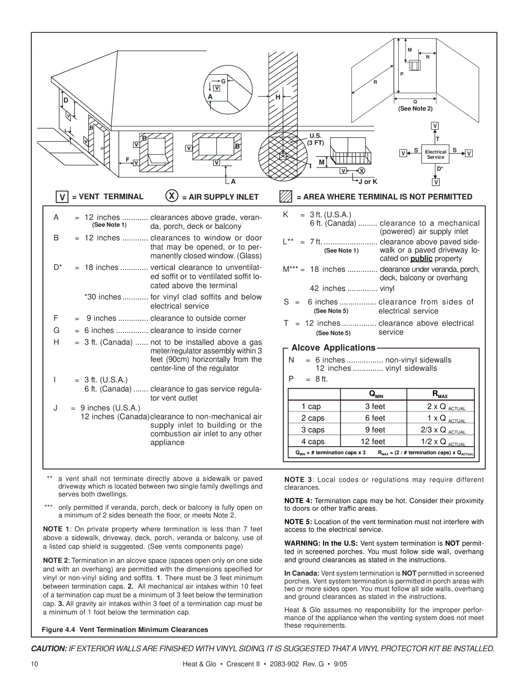
Figure 4.4 Vent Termination Minimum Clearances

NOTE 3: Local codes or regulations may require different clearances.

NOTE 4: Termination caps may be hot. Consider their proximity to doors or other traffic areas.

NOTE 5: Location of the vent termination must not interfere with access to the electrical service.

WARNING: In the U.S: Vent system termination is NOT permit-

ted in screened porches. You must follow side wall, overhang

and ground clearances as stated in the instructions.

In Canada: Vent system termination is NOT permitted in screened porches. Vent system termination is permitted in porch areas with two or more sides open. You must follow all side walls, overhang and ground clearances as stated in the instructions.

Heat & Glo assumes no responsibility for the improper perfor- mance of the appliance when the venting system does not meet these requirements.

CAUTION: IF EXTERIOR WALLS ARE FINISHED WITH VINYL SIDING, IT IS SUGGESTED THAT A VINYL PROTECTOR KIT BE INSTALLED.

10

Heat & Glo • Crescent II • 2083-902 Rev. G • 9/05

Page 10
Image 10
Hearth and Home Technologies Crescent II owner manual Alcove Applications, Vent Termination Minimum Clearances

Crescent II specifications

Hearth and Home Technologies' Crescent II stands as a leading example of cutting-edge fireplace innovation, delivering both aesthetic appeal and efficient warmth to any home. Designed with a focus on user experience, the Crescent II combines modern design with state-of-the-art technology, making it an ideal choice for homeowners seeking both functionality and style in their heating solutions.

One of the standout features of the Crescent II is its sleek contemporary design. The large viewing area, framed by minimalistic lines, creates a striking focal point in any room, allowing homeowners to fully appreciate the mesmerizing dance of flames. Available in various sizes and finishes, the Crescent II can seamlessly integrate into diverse interior styles, from modern to traditional.

The Crescent II is equipped with advanced heating technologies, including a powerful airflow system that optimizes heat distribution throughout the space. This ensures that the warmth is evenly spread, eliminating cold spots that can diminish comfort levels. The unit operates with high efficiency, offering a thermal efficiency rating that meets and often exceeds industry standards, making it an environmentally friendly choice.

In addition to its heating capabilities, the Crescent II features a user-friendly interface, equipped with intuitive controls that make managing the fireplace a breeze. Homeowners can easily adjust the flame height and heat output, allowing for personalized comfort. Some models also come with optional smart technology, enabling remote control via smartphone apps for added convenience.

Another notable characteristic of the Crescent II is its commitment to safety. The unit includes safety features such as a secure glass front that remains cool to the touch, protecting users from burns. The fireplace is designed for venting options that reduce emissions and enhance indoor air quality, ensuring a safe and healthy home environment.

Maintenance is also simplified with the Crescent II. The design allows for easy access to components for cleaning and servicing, providing peace of mind that the fireplace will continue to perform optimally with minimal effort.

In summary, the Hearth and Home Technologies Crescent II is an exceptional fireplace that combines elegance, efficiency, and advanced technology. Its modern aesthetics, powerful heating capabilities, user-friendly controls, and commitment to safety make it a top choice for those looking to add a stylish and functional heating element to their home. With the Crescent II, homeowners can enjoy the warmth and ambiance of a fire while embracing convenience and modern living.