A. Inlet gas supply pressure for purposes of input ad- justment, shall be 6.0 inches w.c. (1.5kPa) for natu- ral gas and 11 inches w.c. (2.75kPa) for propane. Manifold (outlet) pressure should be 3.2 inches w.c. (.80kPa) for natural gas and 9.6 inches w.c. (2.40kPa) for propane models.
B. NOTE: THE GAS SUPPLY LINE SHOULD BE
PURGED OF ANY TRAPPED AIR PRIOR TO THE FIRST FIRING OF THE UNIT.
C. CAUTION: During the initial purging and subse- quent lightings, NEVER allow the gas control valve knob to remain depressed in the "PILOT" position without pushing the red ignitor button at least once every second.
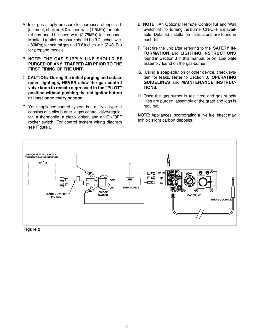
D. Your appliance control system is a millivolt type. It consists of a pilot burner, a gas control valve/regula- tor, a thermopile, a piezo ignitor, and an ON/OFF rocker switch. For control system wiring diagram see Figure 2.
E. NOTE: An Optional Remote Control Kit and Wall Switch Kit , for turning the burner ON/OFF are avail- able. Detailed installation instructions are found in each kit.
F. Test fire the unit after referring to the SAFETY IN- FORMATION and LIGHTING INSTRUCTIONS found in Section 3 in this manual, or on label plate assembly found on the
G.Using a
TIONS.
H.Once the
NOTE: Appliances incorporating a live fuel effect may exhibit slight carbon deposits.
OPTIONAL WALL SWITCH, |
|
| |
THERMOSTAT OR REMOTE |
|
| |
|
| TP/TH | |
| OFF | TP | |
|
| ||
|
| TH | |
| ON | THERMOPILE | |
REMOTE SWITCH | ON/OFF |
| |
SWITCH | GAS VALVE | ||
PIGTAIL | |||
| THERMOCOUPLE | ||
|
|
Figure 2
6