Step 6. The Gas Supply Line

NOTE: Have the gas supply line installed in accordance with local building codes by a qualified installer approved and/or licensed as required by the locality. (In the Commonwealth of Massachusetts installation must be performed by a licensed plumber or gas fitter).

NOTE: Before the first firing of the fireplace, the gas supply line should be purged of any trapped air.

NOTE: Consult local building codes to properly size the gas supply line leading to the 1/2 inch (13 mm) hook-up at the unit.

This gas fireplace is designed to accept a 1/2 inch

(13 mm) gas supply line. To install the gas supply line:

A listed (and Commonwealth of Massachusetts approved) 1/2 inch (13mm) tee-handle manual shut-off valve and a listed flexible gas connector are connected to the 1/2 inch (13mm) inlet of the control valve. NOTE: If substi- tuting for these components, please consult local codes for compliance.

Locate the gas line access hole in the outer casing of the fireplace.

The gas line may be run from either side of the fireplace provided the hole in the outer wrap does not exceed 2” in diameter and it does not penetrate the actual firebox.

Open the fireplace lower grille, insert the gas supply line through the gas line hole, and connect it to the shut-off valve.

When attaching the pipe, support the control so that the lines are not bent or torn.

After the gas line installation is complete, all connec- tions must be tightened and checked for leaks with a commercially-available, non-corrosive leak check solu- tion. Be sure to rinse off all leak check solution following testing.

!WARNING: DO NOT USE AN OPEN FLAME TO CHECK FOR GAS LEAKS.

Insert insulation from the outside of the fireplace and pack the insulation tightly to totally seal between the pipe and the outer casing.

At the gas line access hole the gap between the supply piping and gas access hole can be plugged with non- combustible insulation to prevent cold air infiltration.


USE A WRENCH ON


SHUT-OFF VALVE


WHEN TIGHTENING


GAS LINE.


MANUAL


SHUT-OFF


VALVE


FLEX CONNECTOR


GAS VALVE

GAS LINE

CONTROL VALVE

ACCESS

Figure 33. Gas Supply Line

Step 7. Gas Pressure Requirements

Pressure requirements for Heat & Glo gas fireplaces are shown in the table below.

Pressure

Natural Gas

Propane

Minimum

5.0 inches

11.0 inches

Inlet Pressure

w.c.

w.c.

Maximum Inlet

14.0 inches

14.0 inches

Gas Pressure

w.c.

w.c.

Manifold

3.5 inches

10.0 inches

Pressure

w.c.

w.c.


A one-eighth (1/8) inch (3 mm) N.P.T. plugged tapping is provided on the inlet and outlet side of the gas control for a test gauge connection to measure the manifold pressure.

The fireplace and its individual shut-off valve must be disconnected from the gas supply piping system during any pressure testing of the system at test pressures in excess of one-half (1/2) psig (3.5 kPa).

The fireplace must be isolated from the gas supply piping system by closing its individual shut-off valve during any pressure testing of the gas supply piping system at test pressures equal to or less than one-half (1/2) psig (3.5 kPa).

Heat & Glo • PIER-HVB-IPI, ST-HVB-IPI2006-901 Rev. C • 12/07

31

Page 31
Image 31
Hearth and Home Technologies ST-HVB-IPI, Pier-HVB-IPI owner manual Gas Supply Line, Gas Pressure Requirements

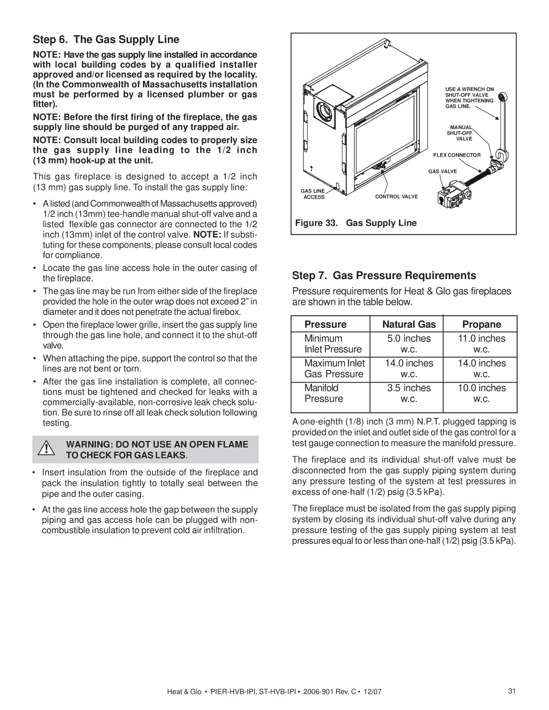
Pier-HVB-IPI, ST-HVB-IPI specifications

Hearth and Home Technologies has made significant strides in the fireplace and heating solutions market with their innovative products, including the ST-HVB-IPI and Pier-HVB-IPI models. These high-efficiency fireplaces promise to bring both functionality and aesthetic appeal to any living space.

The ST-HVB-IPI is designed as a versatile, direct vent gas fireplace that maximizes heat output while maintaining an elegant appearance. One of its standout features is the IntelliFire® Ignition System, which ensures safe and reliable ignition while conserving energy. This system allows for easy operation, making it user-friendly for anyone looking to enjoy a cozy fire with minimal hassle.

In terms of design, the ST-HVB-IPI offers a modern, clean aesthetic that can fit seamlessly into various home styles. With customizable options for fronts, media, and finishes, users can personalize their fireplace to match their décor preferences. Additionally, the large viewing area provides an unobstructed view of the flames, enhancing the ambiance of any room.

The Pier-HVB-IPI, on the other hand, serves as a striking centerpiece in spaces with its unique multi-sided design. This model also utilizes the IntelliFire® Ignition System and is engineered for high thermal efficiency, making it a great option for homeowners looking to optimize their heating without sacrificing style. The Pier model allows for installation in various configurations, promoting versatility in home design.

Both models boast exceptional engineering with a focus on performance. They are equipped with a high-efficiency heat exchanger that maximizes heat output while reducing energy consumption. This feature not only keeps living spaces warm but also enhances overall energy efficiency, which is a growing concern among eco-conscious consumers.

Safety is another key priority for Hearth and Home Technologies. Both fireplaces come designed with safety features such as a safety barrier and optional glass doors that help keep children and pets safe while ensuring the fire remains contained.

In conclusion, the ST-HVB-IPI and Pier-HVB-IPI by Hearth and Home Technologies stand at the intersection of modern design and innovative technology. Offering customizable aesthetics, advanced ignition systems, and enhanced safety and efficiency features, these models are exemplary choices for homeowners seeking to elevate their living environments with elegance and warmth.