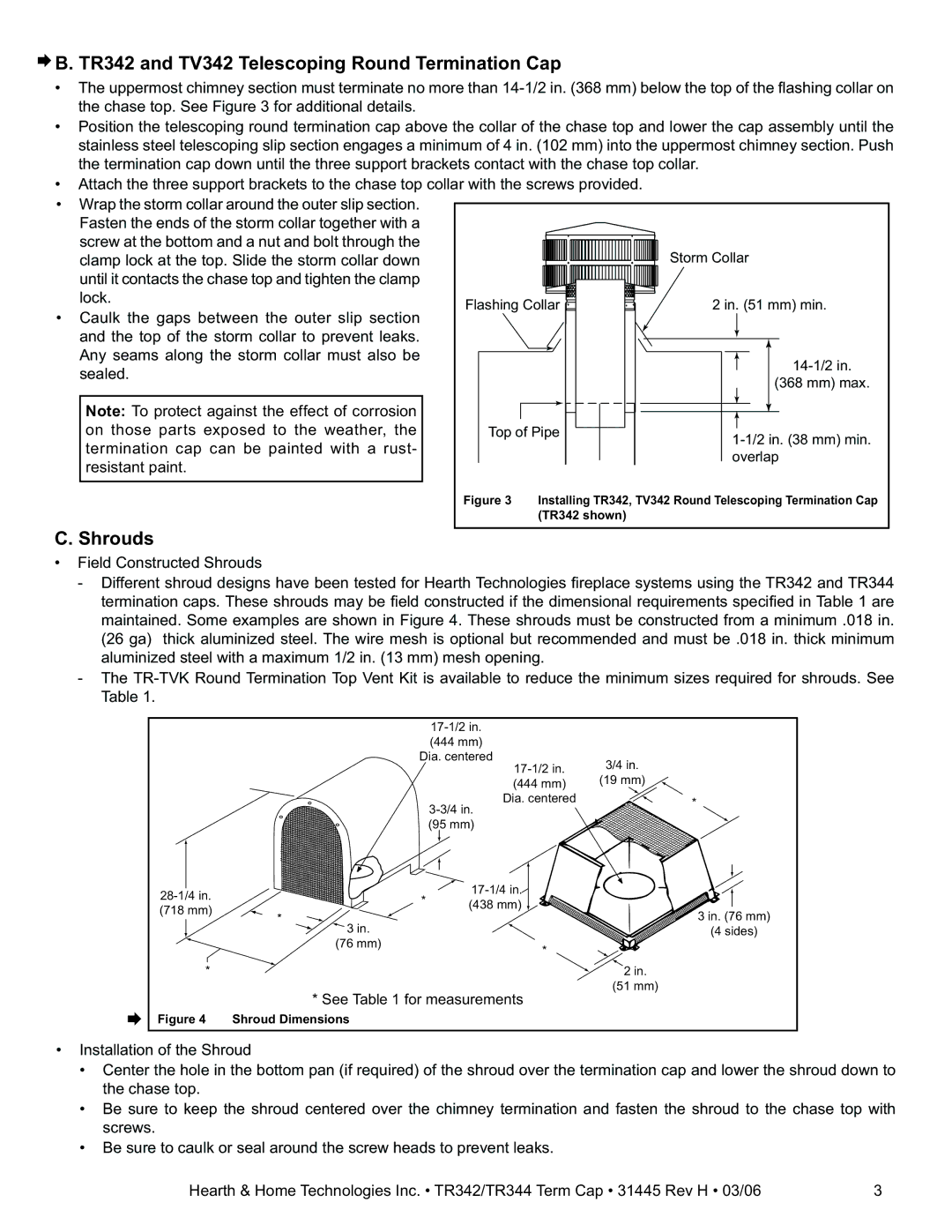
TV342, TR344, TR342 specifications
Hearth and Home Technologies (HHT) has made significant advancements in the realm of home heating solutions with its line of innovative fireplaces, including the TR342, TV342, and TR344 models. Each model brings a unique blend of aesthetics, functionality, and cutting-edge technology, making them ideal for modern homes.The TR342 is designed for versatility and style, featuring a sleek, contemporary design that seamlessly integrates into various home decors. It comes equipped with an array of customizable options, such as different front styles and colors, enabling homeowners to choose a look that complements their living space. The TR342 is also known for its efficient heating capabilities, utilizing a powerful gas burner that provides consistent warmth while maximizing energy efficiency.
In contrast, the TV342 takes the fireplace experience to a new level by incorporating an advanced viewing experience. This model features an impressive glass front, providing unobstructed views of the flames, which creates an inviting atmosphere in any room. The TV342 is also equipped with a state-of-the-art remote control system, allowing users to adjust the flame height and heat output with ease. This flexibility ensures that homeowners can enjoy their fireplace regardless of the season, whether they want a cozy warmth in winter or just the ambiance of a flickering flame in summer.
The TR344 model stands out with its high-efficiency technology that not only reduces fuel consumption but also places a strong emphasis on environmental sustainability. The TR344 utilizes a direct vent system, which provides a safe and efficient way to vent combustion gases outside while drawing in fresh air from the outside for combustion. This feature not only improves safety but also enhances the heating efficiency of the unit, making it a great choice for eco-conscious homeowners.
All three models boast exceptional craftsmanship and durability, utilizing high-quality materials that ensure a long lifespan. Customization options extend beyond aesthetics, as all three models feature adjustable heat settings, timers, and thermostatic controls, allowing users to have complete control over their heating needs. HHT’s commitment to quality is further evidenced by their extensive warranties on these products, offering peace of mind to users.
In conclusion, Hearth and Home Technologies' TR342, TV342, and TR344 models represent the pinnacle of modern fireplace design and functionality. Each model is tailored to cater to diverse preferences and heating requirements, ensuring that homeowners can experience the perfect blend of beauty and warmth in their living spaces.

