Part 3 Test Run

3. Test RunDetail

1.Check that all tubing and wiring have been properly con- nected.

2.Check that the gas and liquid side service valves are fully open.

Settlement of outdoor unit

Anchor the outdoor unit with a bolt and nut Ø0.39 inch tightly and horizontally on a concrete or rigid mount.

When installing on the wall, roof or rooftop, anchor the mounting base securely with a nail or wire assuming the influence of wind and earthquake possibilities.

When vibration of the unit is conveyed through the hose, secure the unit with an anti-vibration bushing.

Bolt

Tubing connection

Evaluation of the performance

Operate unit for 15~20 minutes, then check the system refrigerant charge:

1.Measure the pressure of the gas side service valve.

2.Measure the temperature of the intake and discharge air.

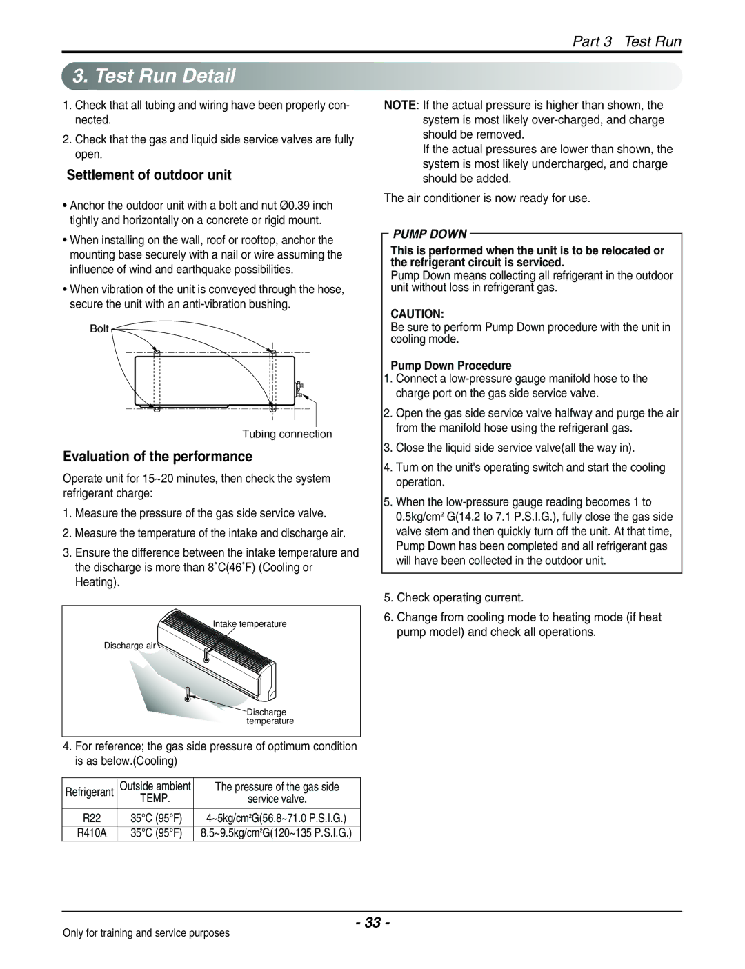
3.Ensure the difference between the intake temperature and the discharge is more than 8˚C(46˚F) (Cooling or Heating).

NOTE: If the actual pressure is higher than shown, the system is most likely over-charged, and charge should be removed.

If the actual pressures are lower than shown, the system is most likely undercharged, and charge should be added.

The air conditioner is now ready for use.

PUMP DOWN

This is performed when the unit is to be relocated or the refrigerant circuit is serviced.

Pump Down means collecting all refrigerant in the outdoor unit without loss in refrigerant gas.

CAUTION:

Be sure to perform Pump Down procedure with the unit in cooling mode.

Pump Down Procedure

1.Connect a low-pressure gauge manifold hose to the charge port on the gas side service valve.

2.Open the gas side service valve halfway and purge the air from the manifold hose using the refrigerant gas.

3.Close the liquid side service valve(all the way in).

4.Turn on the unit's operating switch and start the cooling operation.

5.When the low-pressure gauge reading becomes 1 to 0.5kg/cm2 G(14.2 to 7.1 P.S.I.G.), fully close the gas side valve stem and then quickly turn off the unit. At that time, Pump Down has been completed and all refrigerant gas will have been collected in the outdoor unit.

5.Check operating current.

Intake temperature

Discharge air

Discharge temperature

4.For reference; the gas side pressure of optimum condition is as below.(Cooling)

6.Change from cooling mode to heating mode (if heat pump model) and check all operations.

Refrigerant

Outside ambient

The pressure of the gas side


TEMP.

service valve.

R22

35°C (95°F)

4~5kg/cm2G(56.8~71.0 P.S.I.G.)

R410A

35°C (95°F)

8.5~9.5kg/cm2G(120~135 P.S.I.G.)

- 33 -

Only for training and service purposes

Page 33
Image 33
Heat Controller VMC24SB-1/VMH24SB-1 Test Run Detail, Settlement of outdoor unit, Evaluation of the performance

VMC12SB-1/VMH12SB-1, VMC18SB-1/VMH18SB-1, VMC24SB-1/VMH24SB-1, VMC09SB-1/VMH09SB-1, VMC30SB-1/VMH30SB-1 specifications

The Heat Controller VMC30SB-1/VMH30SB-1, VMC09SB-1/VMH09SB-1, VMC24SB-1/VMH24SB-1, VMC18SB-1/VMH18SB-1, and VMC12SB-1/VMH12SB-1 are versatile and efficient HVAC systems designed for residential and commercial applications. These units stand out due to their innovative technologies, user-friendly features, and reliable performance, making them an excellent choice for heating and cooling needs.

One of the most significant features of these units is their Energy Efficiency Rating (EER). Each model has been engineered to provide optimal energy savings, thus minimizing operating costs and environmental impact. Utilizing advanced inverter technology, the systems adjust their cooling and heating output according to the room's demand, ensuring that energy is used only when necessary. This results in quieter operation, less energy consumption, and enhanced comfort.

The VMC and VMH models are equipped with high-performance compressors that provide rapid heating and cooling capabilities. This feature allows users to attain their desired temperatures more quickly compared to traditional systems, ensuring a comfortable environment throughout the year. In addition, the systems maintain consistent temperatures and reduce temperature fluctuations, contributing to a more enjoyable living or working space.

Another key characteristic of the Heat Controller units is their comprehensive filtration systems. These include multi-stage filters designed to trap dust, allergens, and other particulate matter, contributing to improved indoor air quality. This aspect is particularly important for those who suffer from allergies or respiratory issues, as the units help to create a cleaner, healthier living environment.

The compact design of these models allows for easy installation in various spaces, including small apartments or tight commercial setups. They feature an intuitive control panel that offers user-friendly programming options, enabling users to schedule operations according to their daily routines. Additionally, many models include smart connectivity features, allowing remote access and adjustments via mobile apps.

Finally, the aesthetic design of the VMC and VMH series complements modern interior decors, ensuring that these units not only perform well but look good while doing so. With a combination of reliability, energy efficiency, and user-centric features, the Heat Controller VMC and VMH series stand out as an excellent investment for any heating and cooling requirement. These units promise comfort, convenience, and cost-effective operation.