- -
Chime Replacement Installation
Note: Electrical work must be in accordance with national and local electrical codes. If in doubt, consult a qualified electrician.
1.Verify transformer power rating. Power must be supplied from a 16 Volt AC, 10 Watt or a 16 Volt AC, 15 Watt transformer (Heath®/Zenith models 122C, 121AC, or 125C).
2.Remove cover from existing chime.
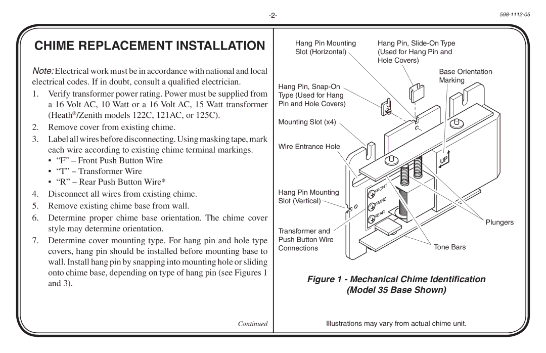
Hang Pin Mounting
Slot (Horizontal)
Hang Pin,
Mounting Slot (x4)
Hang Pin,
Base Orientation
Marking
3. | Label all wires before disconnecting. Using masking tape, mark | |
| each wire according to existing chime terminal markings. | |
| • | “F” – Front Push Button Wire |
| • | “T” – Transformer Wire |
| • “R” – Rear Push Button Wire* | |
4. | Disconnect all wires from existing chime. | |
5. | Remove existing chime base from wall. | |
6. | Determine proper chime base orientation. The chime cover | |
| style may determine orientation. | |
7. | Determine cover mounting type. For hang pin and hole type | |
| covers, hang pin should be installed before mounting base to | |
| wall. Install hang pin by snapping into mounting hole or sliding | |
| onto chime base, depending on type of hang pin (see Figures 1 | |
Wire Entrance Hole
Hang Pin Mounting Slot (Vertical)
Transformer and
Push Button Wire
Connections
ON | T |
| |
FR |
|
S | |
TRAN |
|
REAR |
|
Plungers
Tone Bars
and 3). |
Figure 1 - Mechanical Chime Identification
(Model 35 Base Shown)
Continued
Illustrations may vary from actual chime unit.