ENGLISHIN U.S.A.: Cooper Wiring Devices, 203 Cooper Circle, Peachtree City, GA 30269 •
Energy Management Thermostat Quick Guide — Cat. # RFTSTAT01
Purpose: |
|
|
|
|
|
|
This Quick Guide provides the basic instructions for wiring, installing, and |
|
|
|
|
|
|
programming the Helios thermostat into a | Status |
|
|
|
| Setpoint |
detailed instructions refer to the complete Energy Management |
|
|
|
| ||
Indicator |
|
|
|
| Up/Down | |
Thermostat Installation and Operation Manual. This is located online at |
|
|
|
| ||
LEDs |
|
|
|
| Buttons | |
|
|
|
| |||
www.cooperwiringdevices.com/AspireRF. |
|
|
|
| Heating (H) | |
HVAC System / Thermostat Overview |
|
|
| |||
The RFTSTAT01 connects to the HVAC system’s thermostat connections just | Dynamic |
|
|
| and | |
like a traditional thermostat. | Button |
|
|
| Cooling (C) | |
HVAC System Compatibility | Labels |
|
|
| Setpoints | |
The RFTSTAT01 is compatible with most heating and cooling systems. There |
|
|
|
|
|
|
are two types of HVAC systems: |
|
|
|
|
|
|
|
| Function Control Buttons | ||||
Standard (gas/electric) |
|
| ||||
|
|
|
|
|
| |
Heat Pump systems |
|
|
|
|
|
|
The system type is selectable from the Thermostat Installer Screen by using the Function Control Buttons to access Menu > System Settings
>Mechanical Settings submenu. Refer to the complete Installation and Operation Manual for detailed explanation. Standard HVAC systems: For Gas heating or Electric heating.
Heat Pump HVAC systems: Supports changeover valve operation for either changeover with cooling or changeover with heating.
Multi-Stage HVAC Compatibility:
For Standard HVAC systems the HVAC outputs support 2 stages of heating and 2 stages of cooling.
For Heat Pump HVAC systems, the HVAC outputs support 3 stages of heating (2 compressor/1 Aux Heat) and 2 stages of cooling.
Remote Communications
The RFSTAT01 is embedded with a
WIRING / INSTALLATION
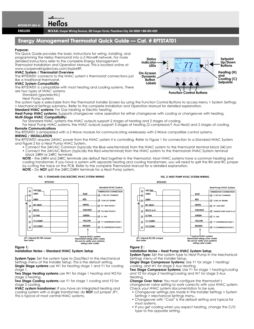
The RFTSTAT01 requires 24VAC power from the HVAC system it is controlling. Refer to Figure 1 for connection to a Standard HVAC System and Figure 2 for a Heat Pump HVAC System.
•Connect the 24V/AC Common (typically the Blue wire/terminal) from the HVAC system to the thermostat terminal block 24Com
•Connect the 24V/AC Return (typically the Red wire/terminal) from the HVAC system to the thermostats HVAC System terminal block 24RH or 24RC terminals
NOTE – the 24RH and 24RC terminals are default tied together in the thermostat. Most HVAC systems have a common heating and cooling transformer. If you have a system with separate heating and cooling transformers, you will need to split the RH and RC jumper by cutting the trace on the PCB. Refer to the complete Thermostat Manual for a detailed explanation.
NOTE – Do NOT split the 24RC/24RH terminals for a Heat Pump system.
|
|
|
|
|
| FIG. 1: STANDARD GAS/ELECTRIC HVAC SYSTEM WIRING | |||||||
|
|
|
|
|
|
| RFTSTAT01 |
|
|
|
|
| |
|
|
|
|
| 24COM |
|
|
|
| Standard HVAC System | |||
|
|
|
|
|
|
|
|
|
| ||||
|
|
|
|
|
|
|
|
|
|
|
| THERMOSTAT CONNECTION | |
|
|
|
|
| 24RC |
|
| BLUE |
| ||||
|
|
|
|
|
|
|
| C 24V/AC COMMON | |||||
|
|
|
|
| 24RH |
| RED |
| R 24V/AC RETURN | ||||
|
|
|
|
| W1 HEAT |
| WHITE |
| |||||
|
|
|
|
|
|
| W 1 HEAT STAGE 1 | ||||||
|
|
|
|
|
|
| |||||||
|
|
|
|
| W2/O |
| ORANGE |
| |||||
|
|
|
|
|
|
| W 2 HEAT STAGE 2 | ||||||
|
|
|
|
| G FAN |
| GREEN |
| |||||
|
|
|
|
|
|
| G FAN | ||||||
|
|
|
|
| Y1 COMP |
| YELLOW |
| |||||
|
|
|
|
|
|
| Y1 COMPRESSOR STAGE 1 | ||||||
|
|
|
|
| Y2 COMP |
| BROWN |
| Y2 COMPRESSOR STAGE 2 | ||||
|
|
|
|
|
|
|
|
|
|
|
| ||
|
|
|
|
|
|
|
|
|
|
|
|
| |
|
|
|
|
|
|
|
|
|
|
|
|
| |
|
|
|
|
|
|
|
|
|
|
| |||
|
|
|
|
|
|
|
|
| Typical HVAC system | ||||
JP1: Internal RC/RH Jumper |
| ||||||||||||
thermostat wiring color codes | |||||||||||||
See notes | |||||||||||||
Be sure to verify your systems | |||||||||||||
|
|
|
|
|
|
|
| ||||||
|
|
|
|
|
|
|
|
| wiring color codes | ||||
Figure 1:
Installation Notes – Standard HVAC System Setup
System Type: Set the system type to Gas/Elect in the Mechanical Settings menu of the Installer Setup. This is the default setting. Single Stage systems use W1 for heating stage 1 and Y1 for cooling stage 1.
Two Stage Heating systems use W1 for stage 1 heating and W2 for stage 2 heating.
Two Stage Cooling systems use Y1 for stage 1 cooling and Y2 for stage 2 cooling.
HVAC system transformer: If you have an integrated heating and cooling system with a single transformer, do NOT cut jumper JP1. This is typical of most central HVAC systems.
|
|
|
|
|
|
| FIG. 2: HEAT PUMP HVAC SYSTEM WIRING |
|
| |||||
|
|
|
|
|
|
| RFTSTAT01 |
|
|
|
|
|
|
|
|
|
|
|
| 24COM |
|
|
|
|
| Heat Pump HVAC System | |||
|
|
|
|
|
|
|
|
|
|
|
| |||
|
|
|
|
|
|
|
|
|
|
|
|
|
| THERMOSTAT CONNECTION |
|
|
|
|
| 24RC |
|
| BLUE |
|
| ||||
|
|
|
|
|
|
|
|
| C 24V/AC COMMON | |||||
|
|
|
|
| 24RH |
| RED |
|
| R 24V/AC RETURN | ||||
|
|
|
|
| W1 HEAT |
| WHITE |
|
| W 1 AUX HEAT | ||||
|
|
|
|
|
|
|
| |||||||
|
|
|
|
| W2/O or B |
| ORANGE |
|
| |||||
|
|
|
|
|
|
|
| CHANGE OVER VALUE O or B | ||||||
|
|
|
|
| G FAN |
| GREEN |
|
| G FAN | ||||
|
|
|
|
| Y1 COMP |
| YELLOW |
|
| Y1 COMPRESSOR STAGE 1 | ||||
|
|
|
|
| Y2 COMP |
| BROWN |
|
| |||||
|
|
|
|
|
|
|
| Y2 COMPRESSOR STAGE 2 | ||||||
|
|
|
|
|
|
|
|
|
|
|
|
|
| |
|
|
|
|
|
|
|
|
|
|
|
|
|
| |
|
|
|
|
|
|
|
|
|
|
|
|
|
|
|
|
|
|
|
|
|
|
|
| Typical |
| HVAC system | |||
|
|
|
|
|
|
|
|
|
| |||||
JP1: Internal RC/RH Jumper | thermostat wiring color codes | |||||||||||||
See notes | Be sure to verify your systems | |||||||||||||
wiring color codes
Figure 2 :
Installation Notes – Heat Pump HVAC System Setup
System Type: Set the system type to Heat Pump in the Mechanical
Settings menu of the Installer Setup. Y1 for stage 1
Single Stage CompW1 foressorstageSystems:2 Aux Useheating/
cooling, andHeatingY1 for. stage 1 heating/cooling
andTwo StageY2 for Compressorstage 2 Systems: Use W1 for
heating/cooling and stage 3 Aux
Heating.
Change Over Valve: You must configure the thermostat’s changeover valve setting to work correctly with your HVAC system. Check your HVAC system documentation to be sure.
•Changeover settings are made in the Installer Settings > System Settings > Mechanical Settings menu.
•Changeover with “Cool” is the default setting and typical for most systems.
•If you get cooling when you expect heating, change the C/O type to the opposite setting.