Manuals
/
Herrmidifier Co
/
Household Appliance
/
Humidifier
Herrmidifier Co
6000
owner manual
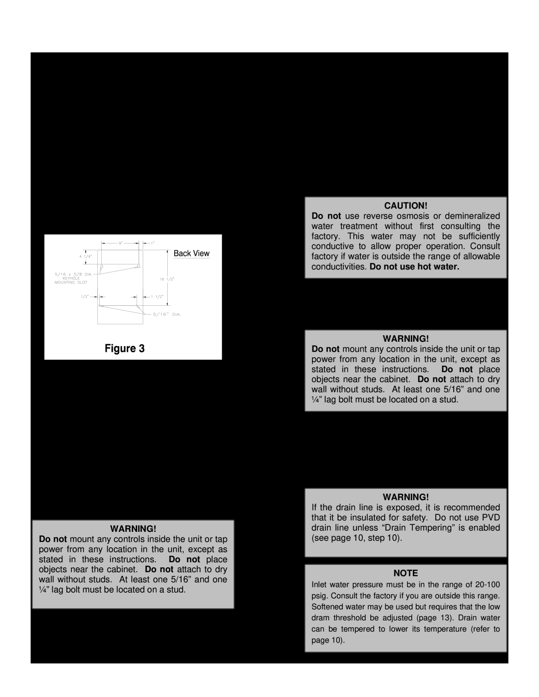
SECTION III INSTALLATION INSTRUCTIONS Mounting, Plumbing
Models:
6000
1
7
24
24
Download
24 pages
7.48 Kb
4
5
6
7
8
9
10
11
Page 7
Image 7
Page 6
Page 8
Page 7
Image 7
Page 6
Page 8
Contents
6000 Series
Installation Operation Service
Electronic Steam Humidifiers
SECTION VI SUGGESTED SPECIFICATIONS
TABLE OF CONTENTS
SECTION III INSTALLATION INSTRUCTIONS
SECTION V TROUBLESHOOTING GUIDE
SECTION I WARRANTY Warranty
SECTION II UNIT OPERATION Basic Operation
Conductivity
Key Features
Adjustable Setpoints
Faults
Allowable Operating Conditions
Engineering and Application
Remove foam packing from top of tank
SECTION III INSTALLATION INSTRUCTIONS Mounting
Plumbing
Distributor Mounting Instructions
Steam Distribution
Blower Version 6000-1,2
DUCTED VERSION 6000-3,4
Control Circuit Connections
Wiring
Figure Supply Power
Electrical Characteristics
SECTION IV OPERATING INSTRUCTIONS
Start-upInstructions
Checklist completion date
Checklist
Checklist completed by
Humidifier Installer Company
Extended Shutdown
Maintenance
To remove the cylinder
Figure 11A Figure 11B
High Conductivity Settings
SECTION V TROUBLESHOOTING GUIDE
Circuit Board Settings
Standard Settings
Fill System Fault
Problem / Symptom
See - NON-FAULTACTIVATED
FAULT ACTIVATED PROBLEMS
Problem / Symptom
Non-FaultActivated Problems
Reason - Correction
Problem / Symptom
Non-FaultActivated Problems - Cont’d
Reason - Correction
Blower Version Wiring Diagram6000-1and
Blower Version Exploded View 6000-1and
Blower Version Parts List 6000-1and
Ducted Version Exploded View 6000-3and
Ducted Version Parts List 6000-3and
Ducted Version Wiring Diagram 6000-3and
Part 3 --Execution
SECTION VI SUGGESTED SPECIFICATIONS
Suggested Specifications Part I-Scope
Part II -Scope
Top
Page
Image
Contents