Mode D’EMPLOI ET Instructions DE Securite
Contents
Product Specifications
Motor SAW
Power Tool Safety
English
Table SAW Safety
Extension Cord Requirements
Electrical Requirements and Safety
Power Supply Requirements
Guidelines for Extension Cords
Carton Contents
Accessories and Attachments
Tools Needed for Assembly
Unpacking Your Jobsite Table SAW
Know Your Jobsite Table SAW
Woodworking Terms
Glossary of Terms
Table SAW Terms
Assemble the Table SAW to the Stand Fig. a
Assembly and Adjustments
Blade Guard Assembly FIG. C, D
Assemble the Handwheel Handle FIG. B
Aligning the Blade Guard Splitter FIG. D
Fig. D
Removing the Blade FIG. E
Installing a Blade FIG. E
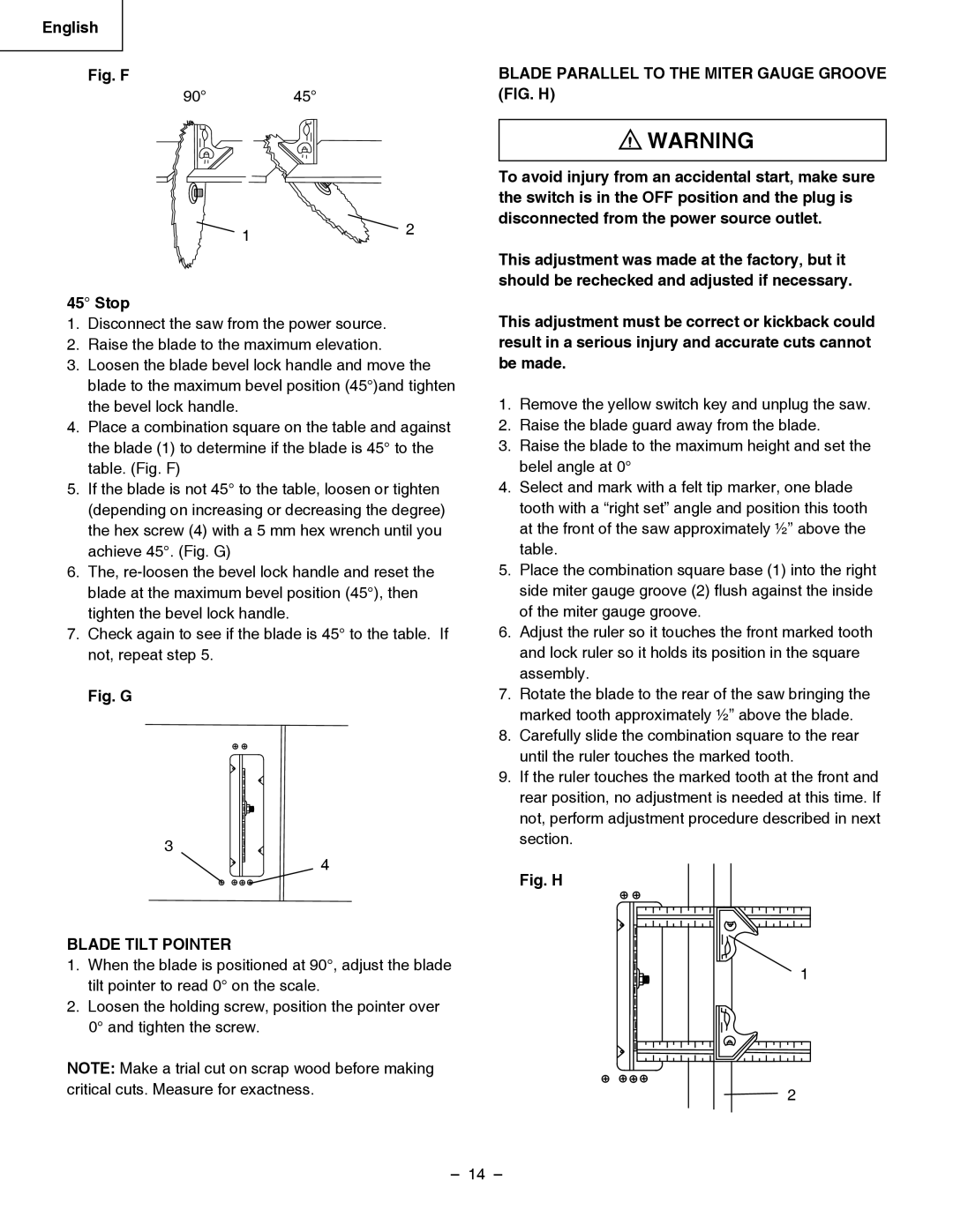
Adjusting the 90 and 45 Positive Stops FIG. F, G
Stop
Blade Tilt Pointer
Blade Parallel to the Miter Gauge Groove FIG. H
Storage FIG. J, K
Additional Blade Adjustments Fig
Installing the Table Insert FIG. L
Rip fence and miter gauge Fig. J
If adjustment is needed to make it parallel
Miter Gauge Adjustment FIG. M
RIP Fence Adjustment FIG. N RIP Fence Indicator FIG. O
Miter Gauge Operation FIG. M
Adjusting CAM Locking Lever FIG. Q
Fig. P
Operation
Basic SAW Operations
Cutting Operations
Ripping FIG. V, W
Ripping Small Pieces
Using Wood Facing on the Miter Gauge Fig
Bevel Ripping
Crosscutting FIG
Miter Cuts FIG. AA
Using Wood Facing on the RIP Fence FIG. BB
Compound Miter Crosscutting FIG. Z
Auxiliary Fence FIG. CC
Dado Cuts FIG. EE
English Attach auxiliary fence to rip fence with two C
Clamps. Fig. DD
Maintaining Your Table SAW
Maintenance
General Maintenance
Lubrication
Troubleshooting Guide
Symptom Possible Causes Corrective Action
Push Stick Construction
Moteur
Fiche Technique DU Produit
Français
Scie
Consignes DE Sécurité SUR LES Outils
Avertissement
Consignes DE Sécurité SUR LA Scie À Table
Alimentation Électrique
Exigences Électriques ET Sécurité
Exigences Concernant L’
Directives DE Mise À LA Terre
Contenu DE LA Boîte
Accessoires
Outils Requis Pour Assemblage
Déballage DE LA Scie À Table DE Chantier
Apprendre À Connaître LA Scie À Table DE Chantier
Termes DE Menuiserie
Glossaire
Termes Relatifs À LA Scie À Table Qualité PRO Craftsman
Assemblage DE LA Poignée DU VOLANTFIG. B
Assemblage ET Réglages
Assemblage DE LA Scie À Table AU Support Fig. a
Assemblage DU PROTÈGE-LAME FIG. C, D
Alignement DU Fendeur ET DU PROTÈGE-LAME
Réglage DES Butées Fixes À 90 ET
Installation D’UNE Lame Fig. E
Retrait DE LA Lame FIG. E
Pour éviter toute blessure causée par une mise en
Indicateur D’INCLINAISON DE Lame
Lame Parallèle À LA Rainure DE LA Jauge À Onglets FIG. H
Rangement FIG. J,K
Installation DU Rangement DU Poussoir FIG. J
Installation DE LA Plaque Amovible FIG. L
Réglage DU Guide DE Refente FIG. N
Reglage DU Guide DE Coupe DE FIL FIG. M
Utilisation DU Guide DE Coupe ’ONGLET FIG. M
Si un réglage est requis pour le rendre parallèle
Indicateur D’ÉCHELLE DE Rallonge DE Table FIG. P
Réglage DU Levier DE Blocage DE Came FIG. Q
Utilisation DE L’ÉJECTEUR DE Sciure FIG. T
Utilisation
Fonctions DE Base DE LA Scie
Inclinaison rapide de la lame
Opérations DE Coupe
Sciage EN Long FIG. V, W
Tronçonnagefig
Coupe EN Long EN Biseau
Coupe EN Long DE Petites Pièces
Tronçonnage EN Biseau FIG. Y
Guide Auxiliaire FIG.CC
Coupe Transversale D’ONGLET DE Type Mixte FIG. Z
Coupes D’ONGLET FIG. AA
De deux serres en « C » Fig. DD
Rainurage FIG. EE
Entretien Général
Entretien
Entretien DE LA Scie À Table
Lubrification
Guide DE Dépannage
Problème Causes Possibles Mesures Correctives
Fabrication D’UN Poussoir
Motor Sierra
Especificaciones DEL Producto
Español
Seguridad DE LA Herramienta Eléctrica
Seguridad EN EL Manejo DE LA Sierra DE Mesa
Requisitos DE LOS Cablesprolongadores
Requisitos Electricos Y Seguridad
Requisitos DE LA Fuente Dealimentación
Indicaciones Para LOS Cablesprolongadores
Accesorios Y Acoples
Contenido DE LA Caja
Cómo Desempacar SU Sierra DE Mesa Para EL Lugar DE Trabajo
Conozca SU Sierra DE Mesa
La parte trasera de la sierra de mesa
Terminos DE Carpinteria
Glosario DE Terminos
Términos DE LA Sierra DE Mesa
Interruptor DE Reinicio POR Sobrecarga
Montaje DEL Mango DEL Volante FIG. B
Montaje Y Ajustes
Montaje DE LA Sierra DE Mesa Sobre EL Soporte Fig. a
Ensamblado DEL Protector DE LA Hoja FIG. C, D
Cómo Alinear EL Separador DEL Protector DE LA Hoja FIG. D
Cómo Extraer LA Hoja FIG. E
Ajuste DE LOS Topes DE Seguridad a 90 Y
Indicador DE Inclinación DE LA Hoja
Alineacion DE LA Hoja CON LA Ranura DEL
Cartabon DE Ingletes FIG. H
Cómo Instalar EL Inserto DE Mesa FIG. L
Installing the PUSH-STICK Storage FIG. J
Almacenaje FIG. J, K
Ingletes Fig. M
Español Ajuste DE LA Guía DE Ingletes Fig. M
Funcionamiento DE LA Guía DE
Ajuste DE LA Guía DE Corte FIG. N
Indicador DE LA Escala DE Extensión DE LA Mesa FIG. P
Cómo Ajustar LA Palanca DE Bloqueo DE LA Leva FIG. Q
Inclinación DE LA Hoja
Funcionamiento
Funcionamiento Elemental DE LA Sierra
Cómo Usar EL Conducto Para EL Aserrín FIG. T
Operaciones DE Corte
Corte EN Direccion a LA Veta FIG. V, W
Corte Transversal FIG
Corte AL Hilo EN Bisel
Corte AL Hilo DE Piezas Pequeñas
USO DE Caras DE Madera EN LA Guía DE Ingletes Fig
Fabricación del lateral
Corte Compuesto DE Ingletes FIG. Z
Union DE Inglete FIG. AA
Ensamblaje de las dos piezas
En forma de C. Fig. DD
Cortes DE Ranura FIG. EE
Mantenimiento General
Mantenimiento
Mantenimiento DE LA Sierra DE Mesa
Mecanismo DE LA Lamina ELEVATION/TILTING FIG. FF
Guia Para LA Solucion DE Problemas
Problema Causas DEL Problema Solucion
Construccion DEL Empujador
JOB Site Table SAW Model NO. C10RB
Parts List
Parts List for Schematic
Always order by I.D. Number
JOB Site Table SAW
Parts List for Stand
HKU#
Page
Hitachi Koki Canada Co