4. Confirm the power receptacle
If the power receptacle only loosely accepts the plug, the receptacle must be repaired. Contact the nearest electric store for repair service.
If such a faulty receptacle is used, may cause overheating, resulting in a serious hazard.
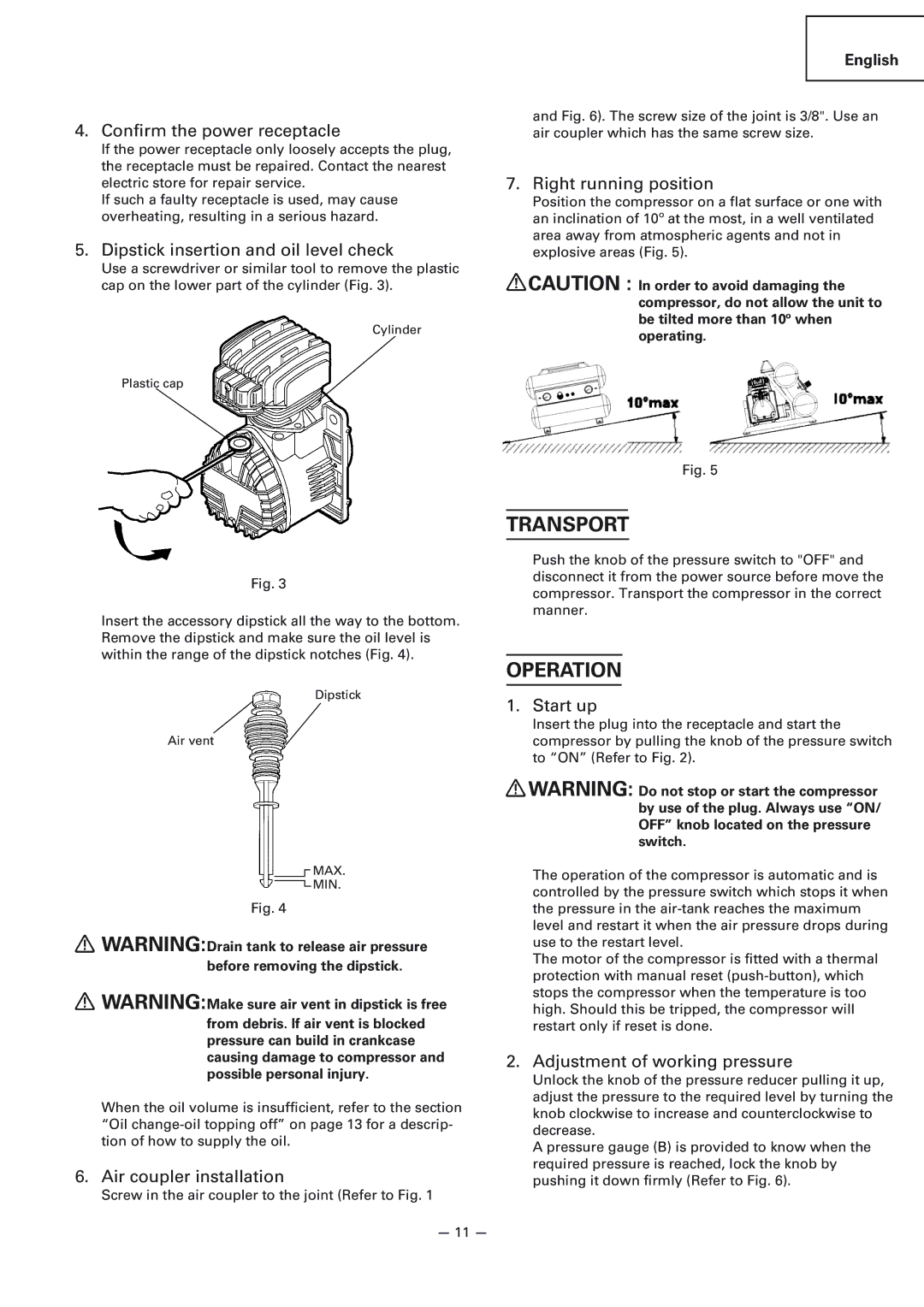
5. Dipstick insertion and oil level check
Use a screwdriver or similar tool to remove the plastic cap on the lower part of the cylinder (Fig. 3).
Cylinder
Plastic cap
Fig. 3
Insert the accessory dipstick all the way to the bottom. Remove the dipstick and make sure the oil level is within the range of the dipstick notches (Fig. 4).
Dipstick
Air vent
![]() MAX.
MAX.
![]() MIN.
MIN.
Fig. 4
![]() WARNING:Drain tank to release air pressure before removing the dipstick.
WARNING:Drain tank to release air pressure before removing the dipstick.
![]() WARNING:Make sure air vent in dipstick is free from debris. If air vent is blocked pressure can build in crankcase causing damage to compressor and possible personal injury.
WARNING:Make sure air vent in dipstick is free from debris. If air vent is blocked pressure can build in crankcase causing damage to compressor and possible personal injury.
When the oil volume is insufficient, refer to the section “Oil
6. Air coupler installation
Screw in the air coupler to the joint (Refer to Fig. 1
English
and Fig. 6). The screw size of the joint is 3/8". Use an air coupler which has the same screw size.
7. Right running position
Position the compressor on a flat surface or one with an inclination of 10º at the most, in a well ventilated area away from atmospheric agents and not in explosive areas (Fig. 5).
![]() CAUTION : In order to avoid damaging the compressor, do not allow the unit to be tilted more than 10º when operating.
CAUTION : In order to avoid damaging the compressor, do not allow the unit to be tilted more than 10º when operating.
Fig. 5
TRANSPORT
Push the knob of the pressure switch to "OFF" and disconnect it from the power source before move the compressor. Transport the compressor in the correct manner.
OPERATION
1. Start up
Insert the plug into the receptacle and start the compressor by pulling the knob of the pressure switch to “ON” (Refer to Fig. 2).
![]() WARNING: Do not stop or start the compressor by use of the plug. Always use “ON/ OFF” knob located on the pressure switch.
WARNING: Do not stop or start the compressor by use of the plug. Always use “ON/ OFF” knob located on the pressure switch.
The operation of the compressor is automatic and is controlled by the pressure switch which stops it when the pressure in the
The motor of the compressor is fitted with a thermal protection with manual reset
2. Adjustment of working pressure
Unlock the knob of the pressure reducer pulling it up, adjust the pressure to the required level by turning the knob clockwise to increase and counterclockwise to decrease.
A pressure gauge (B) is provided to know when the required pressure is reached, lock the knob by pushing it down firmly (Refer to Fig. 6).
— 11 —