1 | 2 | 3 | 4 |
A
B
C
D
E
F
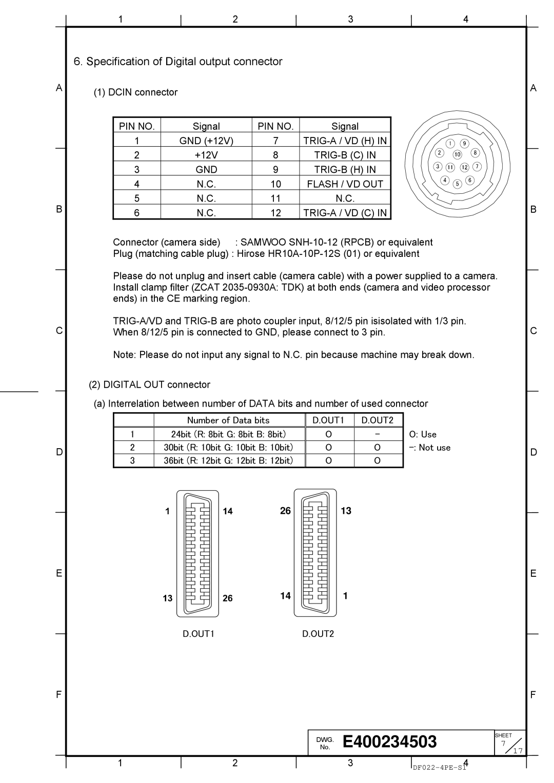
6.Specification of Digital output connector
(1)DCIN connector
PIN NO. | Signal |
| PIN NO. | Signal |
|
1 | GND (+12V) |
| 7 |
|
|
2 | +12V |
| 8 |
|
|
3 | GND |
| 9 |
|
|
4 | N.C. |
| 10 | FLASH / VD OUT |
|
5 | N.C. |
| 11 | N.C. |
|
6 | N.C. |
| 12 |
|
|
Connector (camera side) | : SAMWOO | ||||
Plug (matching cable plug) : Hirose
Please do not unplug and insert cable (camera cable) with a power supplied to a camera. Install clamp filter (ZCAT
Note: Please do not input any signal to N.C. pin because machine may break down.
(2) DIGITAL OUT connector
(a) Interrelation between number of DATA bits and number of used connector
|
| Number of Data bits | D.OUT1 | D.OUT2 |
| |||||||||||||
|
|
|
|
|
|
|
|
|
|
|
|
|
|
|
|
|
|
|
1 | 24bit (R: 8bit G: 8bit B: 8bit) |
|
|
| O | - | O: Use | |||||||||||
|
|
|
|
|
|
|
|
|
|
|
|
|
|
|
|
|
|
|
2 | 30bit (R: 10bit G: 10bit B: 10bit) |
|
|
| O | O | ||||||||||||
|
|
|
|
|
|
|
|
|
|
|
|
|
|
|
|
|
|
|
3 | 36bit (R: 12bit G: 12bit B: 12bit) |
|
|
| O | O |
| |||||||||||
|
|
|
|
|
|
|
|
|
|
|
|
|
|
|
|
|
|
|
|
|
|
|
|
|
| 26 |
|
|
|
|
|
| 13 |
|
| ||
|
|
|
|
|
|
|
|
|
|
|
|
|
|
| ||||
|
|
|
|
|
|
|
|
|
|
|
|
|
| |||||
|
|
|
|
|
|
|
|
|
|
|
|
|
| |||||
|
|
|
|
|
|
|
|
|
|
|
|
|
|
|
|
|
|
|
|
|
|
|
|
|
|
|
|
|
|
|
|
|
|
|
|
|
|
|
|
|
|
|
|
|
|
|
|
|
|
|
|
|
|
|
|
|
|
|
|
|
|
|
|
|
|
|
|
|
|
|
|
|
|
|
|
|
|
|
|
|
|
|
|
|
|
|
|
|
|
|
|
|
|
|
|
|
|
|
|
|
|
|
|
|
|
|
|
|
|
|
|
|
|
|
|
|
|
|
|
|
|
|
|
|
|
|
|
|
|
|
|
|
|
|
|
|
|
|
|
|
|
|
|
|
|
|
|
|
|
|
|
|
|
|
|
|
|
|
|
|
|
|
|
|
|
|
|
|
|
|
|
|
|
|
|
|
|
|
|
|
|
|
|
|
|
|
|
|
|
14 ![]()
![]() 1
1
D.OUT1D.OUT2
|
|
| DWG.No. | E400234503 |
| 7 |
| |
|
|
|
|
|
|
| SHEET |
|
|
|
|
|
|
|
|
| 17 |
1 | 2 |
|
| 3 |
| 4 |
|
|
|
|
|
|
|
|
| ||
A
B
C
D
E
F