English
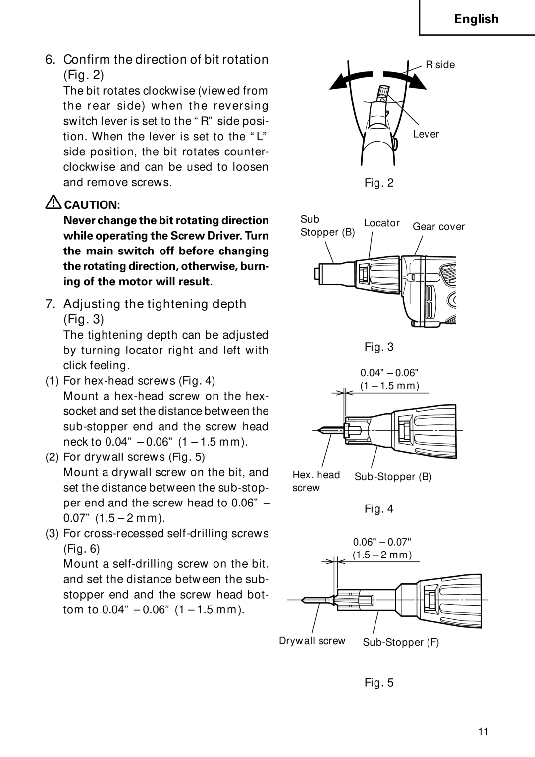
6.Confirm the direction of bit rotation (Fig. 2)
The bit rotates clockwise (viewed from the rear side) when the reversing switch lever is set to the “R” side posi- tion. When the lever is set to the “L” side position, the bit rotates counter- clockwise and can be used to loosen and remove screws.
![]() CAUTION:
CAUTION:
Never change the bit rotating direction while operating the Screw Driver. Turn the main switch off before changing the rotating direction, otherwise, burn- ing of the motor will result.
7.Adjusting the tightening depth (Fig. 3)
The tightening depth can be adjusted by turning locator right and left with click feeling.
(1)For
Mount a
(2)For drywall screws (Fig. 5)
Mount a drywall screw on the bit, and set the distance between the
(3)For
Mount a
R side
Lever
Fig. 2
Sub | Locator | Gear cover | |
Stopper (B) | |||
| |||
|
|
Fig. 3
0.04" – 0.06" (1 – 1.5 mm)
Hex. head
Fig. 4
0.06" – 0.07" (1.5 – 2 mm)
Drywall screw
Fig. 5
11
