Hobie 18 SE, 18 SX manual Mast Assembly

Models: 18 SX 18 SE

1 34
Download 34 pages 36.19 Kb
Page 9
Image 9

MAST ASSEMBLY

1.Support mast at both ends on saw horses or other such devices. Ref: Illus. #1, Pg. 20.

2.Spreaders. In the rig kit you will find all the parts of the spreader assembly.

3.The larger of the two pairs of aluminum rods (1-1), is the spreader arm. Attach it to the aft tab of the spreader root (1-2). Use a 3/16" x 11/16" clevis pin (1-3). turnbuckle on the bolt, pass the bolt through the mast at the compression sleeve which is located 1 foot above the mast base(1-14). The shackled end of the MRCY should be behind the mast.

4.Locate the slide (1-4) on the spreader arm so that the large wing of the slide is closest to the mast, and facing forward.

5.Line up the inboard hole on the slide with the outboard hole on the spreader arm and insert the slide adjustment pin 3/16" x 13/16" (1-5). The slide is now positioned in the raked forward attitude.

6.Connect the smaller brace rod (1-6) between the forward tab on the spreader root and the wing on the slide, with the brace pin 3/16" x 9/16" (1-7).

7.Secure all the clevis pins with the cotter keys provided.

8.Repeat steps 3-7 for the opposite side of the mast.

9.There will be two large cotter pins (1-8) left over, place them to one side, they will be used later to retain the diamond wires in the spreader arm tips.

10.Mast rotation control yoke (MRCY). In the rig kit you will find the parts of the MRCY. You will also need the diamond wires which can be identified by the turnbuckles on one end.

11.IMPORTANT follow this sequence to assemble the MRCY and diamond wires.

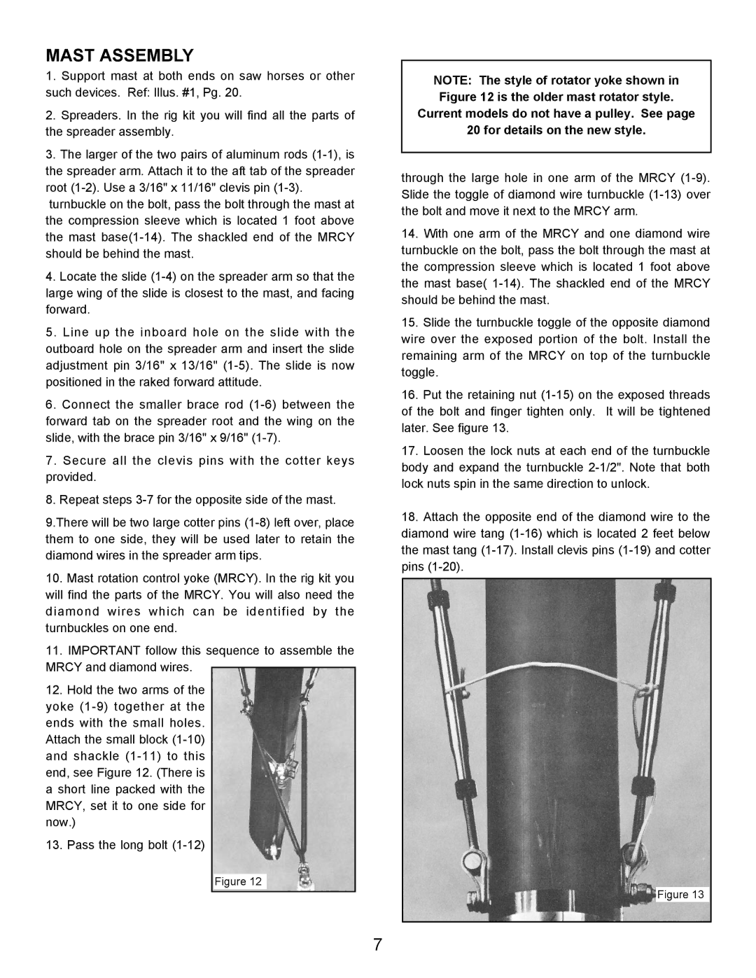
12.Hold the two arms of the

yoke (1-9) together at the ends with the small holes. Attach the small block (1-10) and shackle (1-11) to this end, see Figure 12. (There is a short line packed with the MRCY, set it to one side for now.)

13. Pass the long bolt (1-12)

Figure 12

NOTE: The style of rotator yoke shown in Figure 12 is the older mast rotator style.

Current models do not have a pulley. See page

20 for details on the new style.

through the large hole in one arm of the MRCY (1-9). Slide the toggle of diamond wire turnbuckle (1-13) over the bolt and move it next to the MRCY arm.

14.With one arm of the MRCY and one diamond wire turnbuckle on the bolt, pass the bolt through the mast at the compression sleeve which is located 1 foot above the mast base( 1-14). The shackled end of the MRCY should be behind the mast.

15.Slide the turnbuckle toggle of the opposite diamond wire over the exposed portion of the bolt. Install the remaining arm of the MRCY on top of the turnbuckle toggle.

16.Put the retaining nut (1-15) on the exposed threads of the bolt and finger tighten only. It will be tightened later. See figure 13.

17.Loosen the lock nuts at each end of the turnbuckle body and expand the turnbuckle 2-1/2". Note that both lock nuts spin in the same direction to unlock.

18.Attach the opposite end of the diamond wire to the diamond wire tang (1-16) which is located 2 feet below the mast tang (1-17). Install clevis pins (1-19) and cotter pins (1-20).

Figure 13

7

Page 9
Image 9
Hobie 18 SE, 18 SX manual Mast Assembly