Manning EC-P2, EC-P2 specifications
The Honeywell EC-P2 is a sophisticated and versatile product designed for enabling efficient monitoring and management of various building systems. This advanced device is particularly popular among facility managers and operational teams for its exceptional features and robust technology that enhance the overall functionality of building automation.One of the standout features of the Honeywell EC-P2 is its dual communication capability. It integrates seamlessly with both BACnet and Modbus protocols, enabling effective interoperability within diverse building management systems. This flexibility allows users to connect various devices and sensors, creating a unified and streamlined infrastructure.
The EC-P2 is equipped with advanced sensor technology that provides real-time data on numerous environmental parameters. By accurately monitoring variables such as temperature, humidity, and air quality, the device plays a crucial role in optimizing indoor comfort and energy efficiency. This real-time monitoring helps facility managers make informed decisions and deploy strategies that reduce energy consumption and operating costs.
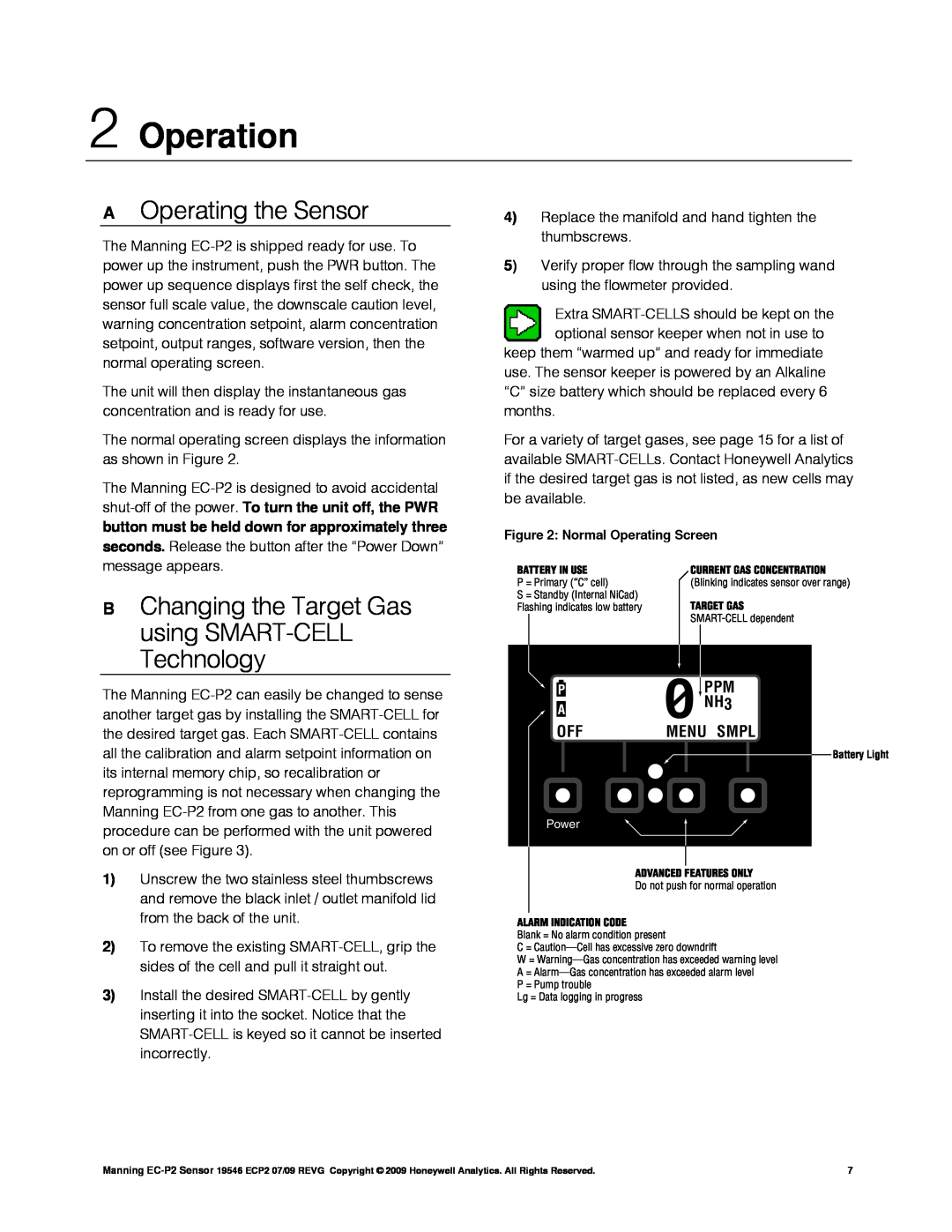
Another notable characteristic of the Honeywell EC-P2 is its user-friendly interface. The device comes with an intuitive display that provides easy access to key parameters and system statuses. Users can easily configure settings and troubleshoot any issues directly through the interface, minimizing downtime and improving operational efficiency.
In terms of expandability, the EC-P2 offers multiple I/O options, making it versatile enough to handle various applications. This expandability allows for integration with additional sensors and control devices, ensuring that the system can grow alongside changing operational needs.
Notably, the EC-P2 is designed with security in mind. It incorporates robust security measures to safeguard data and ensure safe communication over the network. This focus on security is increasingly important in today’s connected environments, where cybersecurity threats pose significant risks.
Finally, the Honeywell EC-P2 stands out for its reliability and durability. Built with quality components and rigorous testing standards, it is engineered to function effectively in demanding environments. Whether used in commercial buildings, industrial settings, or educational institutions, the EC-P2 is a trusted solution for modern building management needs.
With its advanced features, wide-ranging compatibility, and focus on efficiency and security, the Honeywell EC-P2 is a pivotal component in creating intelligent, responsive, and sustainable building environments. Its integration capabilities and user-centric design make it an invaluable tool for optimizing operational performance in today's fast-evolving technological landscape.
