Safety Non Contact Switch FF-SNC
•Complies with the requirements of the EN
•Meets applicable parts of ANSI/RIA/OSHA regulations
Suitable for interfaces
up to
CATEGORY 3
per EN
Dimensions in millimeters / inches, meters / feet, weights in kg / lbs | C U® L US LISTED | ||
|
| ||
|
|
|
|
Features |
|
|
|
Switch |
|
|
|
Material | ABS | ||
Sensing range | 5 mm - 7 mm / 0.20 in - 0.27 in ON • | 8 mm - 12 mm / 0.32 in - 0.47 in OFF |
|
| allowable misalignment: ±4mm / ±1/6 in |
| |
Minimum gap | 1 mm |
| |
Standard cable length | Prewired 3 m / 9.84 ft or 5 m/16.4 ft (ABS only) - M8 plug: 5 mm/16.4 ft (ABS only) |
| |
Temperature | Operating: |
| |
Connection to the control unit | Max. cable length: 100 m / 328 ft | ||
Sealing | IP 67 prewired or M8 plug |
| |
Fixing | 2 x (M4 x 20 mm) Tamper proof screws (supplied with the product) | ||
Control unit / extension module |
|
|
|
Category | Category 3 according to EN | ||
Supply voltage | 24 Vdc/Vac ±15 % • 110 Vac ±15 % |
| |
Response time of the control unit | 15 ms (with or without extension module) | ||
Power consumption (including sensors) | 6 VA (with or without ext. module): |
| |
Temperature | Operating : | • Storage: |
|
Output | 2 NO + 1 NC relay contact |
| |
Output Contact Rating | Max.: 4 A / 230 Vac; 2 A / 24 Vdc (Res.) @Cos = 1 • Min.: 10 V / 10 mA | ||
Restart | Manual or automatic |
| |
Sealing | IP 40 Housing, Terminals IP 20 | ||
|
|
| |
Mounting | 35 mm / 1.37 in DIN rail | ||
LED indicators |
| ||
| |||
Material | Polycarbonate, red |
| |
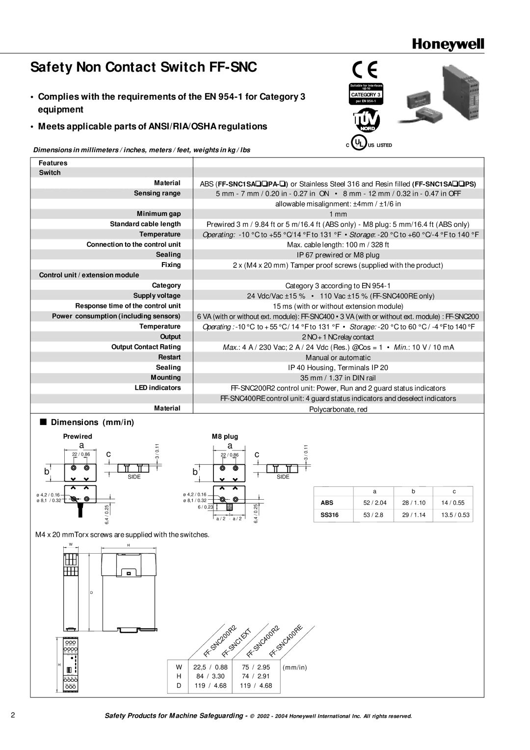
■Dimensions (mm/in)
Prewired
a
22 / 0.86
b
ø 4,2 / 0.16 ø 8,1 / 0.32
c
SIDE
6,4 / 0.25
3 / 0.11
M8 plug
a
22 / 0.86
b
ø 4,2 / 0.16 ø 8,1 / 0.32
6 / 0.23
a / 2 a / 2
c
SIDE
6,4 / 0.25![]()
3 / 0.11
|
| a | b | c |
ABS | 52 | / 2.04 | 28 / 1.10 | 14 / 0.55 |
SS316 | 53 | / 2.8 | 29 / 1.14 | 13.5 / 0.53 |
M4 x 20 mmTorx screws are supplied with the switches.
WH
D
DR DR DR
A1 BL BL BL
GATE 1 GATE 2 GATE 3
H
GATE 4 GATE 5
A2 BL BL BL
DR DR DR
|
| SNC200R2 |
|
| SNC400RE | ||
| - | ||||||
| FF |
| FF | FF | FF |
|
|
W | 22,5 / 0.88 | 75 | / 2.95 |
| (mm/in) | ||
H | 84 / 3.30 | 74 | / 2.91 |
|
| ||
D | 119 / 4.68 | 119 / 4.68 |
|
| |||
|
|
|
|
|
|
|
|
2 | Safety Products for Machine Safeguarding - © 2002 - 2004 Honeywell International Inc. All rights reserved. |
