HMR3100
SENSOR PRODUCTS
Continuous Mode
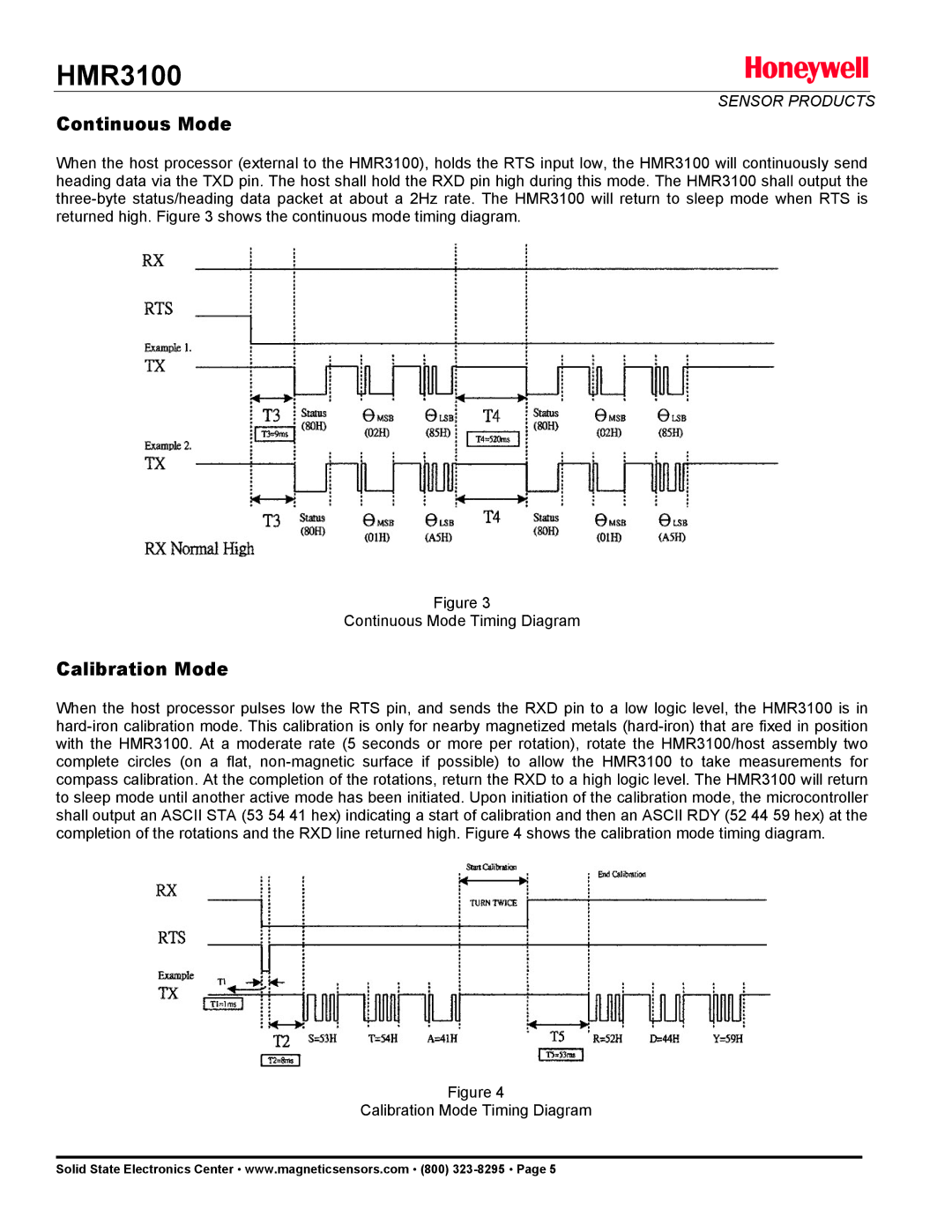
When the host processor (external to the HMR3100), holds the RTS input low, the HMR3100 will continuously send heading data via the TXD pin. The host shall hold the RXD pin high during this mode. The HMR3100 shall output the three-byte status/heading data packet at about a 2Hz rate. The HMR3100 will return to sleep mode when RTS is returned high. Figure 3 shows the continuous mode timing diagram.
Figure 3
Continuous Mode Timing Diagram
Calibration Mode
When the host processor pulses low the RTS pin, and sends the RXD pin to a low logic level, the HMR3100 is in hard-iron calibration mode. This calibration is only for nearby magnetized metals (hard-iron) that are fixed in position with the HMR3100. At a moderate rate (5 seconds or more per rotation), rotate the HMR3100/host assembly two complete circles (on a flat, non-magnetic surface if possible) to allow the HMR3100 to take measurements for compass calibration. At the completion of the rotations, return the RXD to a high logic level. The HMR3100 will return to sleep mode until another active mode has been initiated. Upon initiation of the calibration mode, the microcontroller shall output an ASCII STA (53 54 41 hex) indicating a start of calibration and then an ASCII RDY (52 44 59 hex) at the completion of the rotations and the RXD line returned high. Figure 4 shows the calibration mode timing diagram.
Figure 4
Calibration Mode Timing Diagram
Solid State Electronics Center • www.magneticsensors.com • (800) 323-8295 • Page 5