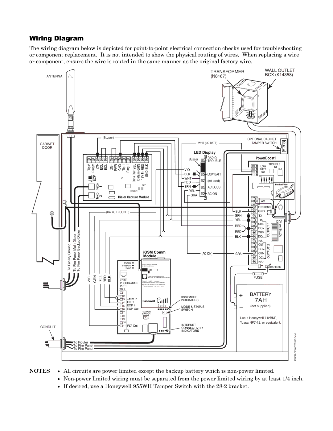
Wiring Diagram

The wiring diagram below is depicted for point-to-point electrical connection checks used for troubleshooting or component replacement. It is not intended to show the physical routing of wires. When replacing a wire or component, ensure the wire is routed in the same manner as the original factory wire.


TRANSFORMER

WALL OUTLET


BOX (K14358)

ANTENNA

(N8167)


CABINET

DOOR

(Buzzer)

WHT (LO BATT)

LED Display

Buzzer RADIO TROUBLE

OPTIONAL CABINET TAMPER SWITCH

PowerBoost1

Tip 2 Ring 2 ZN- EOL EOL

ZN+ PWR GND Tip 1 Ring 1

YEL

in GRN

RED

Out

V In NBLKD


VIO


BLK

LOW BATT

LOW BATT

TROUBLE

ECP

Data Data 12 G

Telco 1

RED

GREEN

Telco 2

Dialer Capture Module

WHT

(not used)

RED


BRN

AC LOSS

YEL

AC ON

GRA


ON


1

2

3

4

5

(RADIO TROUBLE)

BLK GRN YEL

RED

AC


ERTH GND


GND


TX


RX


AC

OUT+

1


DC+


E

Facility Ground

Fire Panel Main Dialer

Fire Panel Backup Dialer

To

To

To

STATUS

MESSAGE

FAULT


iGSM Comm


(AC ON)


Module


FOR EXTERNAL ANTENNA


50 OHM MMCX ONLY


RED

BLK

GRA

OUT-

OUTPUT


ACTIV


DC-


N/U


OUT+

2


DC+

OUTPUT


OUT-


DC-


N/U


BATTERY


VIO

GRN

YEL

RED

CONDUIT

To Router

To Fire Panel

To Fire Panel

BLK


7720P


PROGRAMMER


PORT


TB 1


1


2

+12V In


3


4

GND


5

ECP In


6

ECP Out


7


8


9


10


11

FLT Out


7720P PROGRAMMER PORT


NOT FOR TELEPHONE SERVICE USE!


PRIMARY POWER: 9 - 16.5 VAC


CURRENT: 900mA PEAK, 70mA STANDBY


BATTERY: 8V. 3.1 AHr FOR 24 Hr BACKUP


FCC:XXXXXXXXXX IC: YYYYYYYYYY


RSSI/MODE


GPRS M1 M0 RSSI

IBS


INDICATORS


MODE & STATUS

TAMPER


SWITCH


SWITCH


INTERNET


CONNECTIVITY


INDICATORS

FUSE

+BATTERY

7AH

(not supplied)

Use a Honeywell 712BNP,

Yuasa NP7-12, or equivalent.

IPGSM-DP-007-V2 [US Only]

NOTES All circuits are power limited except the backup battery which is non-power limited.

Non-power limited wiring must be separated from the power limited wiring by at least 1/4 inch.

If desired, use a Honeywell 955WH Tamper Switch with the 28-2 bracket.

Page 15
Image 15
Honeywell IPGSM-DP manual Wiring Diagram, + Battery

IPGSM-DP specifications

The Honeywell IPGSM-DP is an advanced communication device specifically designed for alarm signaling and monitoring in contemporary security systems. This state-of-the-art unit is engineered to enhance the efficiency and reliability of alarm communications, serving as an integral part of home and business security solutions.

One of the main features of the IPGSM-DP is its dual-path communication capability, allowing it to connect via both cellular networks and the internet. This dual communication method ensures that security signals are transmitted even in situations where traditional phone lines may fail or be compromised. This capability is particularly crucial in maintaining a reliable line of communication between alarm systems and monitoring stations.

In terms of technology, the IPGSM-DP utilizes a robust GSM (Global System for Mobile Communications) module for cellular communication. This technology provides high-speed data transmission, which is essential for sending real-time alerts and notifications to security personnel or end-users. This feature enhances the overall responsiveness of the alarm system, enabling swift action in the event of a security breach.

Moreover, the IPGSM-DP is compatible with various alarm control panels, making it a versatile addition to existing security setups. It seamlessly integrates with both Honeywell and third-party systems, allowing users to upgrade their alarm capabilities without overhauling their entire security infrastructure.

The device also boasts advanced encryption technology, which serves to protect the integrity of the communication channels. This security feature is vital in safeguarding sensitive information and ensuring that alarm signals cannot be intercepted or tampered with.

In terms of characteristics, the IPGSM-DP is designed with user-friendliness in mind. It comes with an intuitive LED indicator that provides visual feedback on operational status, signal strength, and any potential issues that may arise. The compact design allows for easy installation in various locations within a property, minimizing disruption to the environment.

Furthermore, the Honeywell IPGSM-DP supports multiple protocols, including Contact ID and SIA, thereby ensuring compatibility with a wide range of monitoring stations and allowing for flexible deployment in diverse security scenarios. Enhanced diagnostic capabilities further simplify troubleshooting and maintenance of the device, ensuring long-term reliability.

In summary, the Honeywell IPGSM-DP is a cutting-edge communication device offering dual-path communication, GSM technology, compatibility with multiple alarm systems, and advanced security features. Its distinctive characteristics make it an excellent choice for enhancing the efficiency and reliability of alarm monitoring and signaling in various security applications.