SERIES 90 MODUTROL IV™ MOTORS

Auxiliary Switch Adjustment

1.Remove the top cover from the motor to gain access to the motor terminals and auxiliary cams.

2.Disconnect the controller from the motor.

3.Connect a potentiometer to the motor as shown in Fig. 7.

4.Using the potentiometer, drive the motor to the position where the auxiliary equipment is to be switched.

5.For a 1° switch differential, check continuity of the auxiliary switch contacts R-B and rotate the cam as follows:

a.If the contacts are open, rotate the cam clockwise until the R-B contacts close.

b.If the contacts are closed, rotate the cam counterclockwise until the R-B contacts open.

6.For a 10° switch differential:

a.Spring return models: rotate the cam approximately 180° so that the slow-rise portion of the cam actuates the switch. Then check continuity of the auxiliary switch contacts R-B

b.Non-spring return models: check continuity of the auxiliary switch contacts R-B.

7.Rotate the cam as follows:

a.If the contacts are open, rotate the cam counterclockwise until the R-B contacts close.

b.If the contacts are closed, rotate the cam clockwise until the R-B contacts open.

8.Check for proper auxiliary equipment differential and switching by driving the motor though the full stroke in both directions.

9.Disconnect the potentiometer, reconnect the controller, and replace the motor top cover.

NOTE: Changing the differential from 1° to 10° reverses the switching action. For example, with a 10° differential, switch contacts R-B make and R-W break on a counterclockwise (closed) rotation. With a 1° differential, switch contacts R-W make and R-B break on a counterclockwise (closed) rotation.

OPERATION

Use Series 90 Modutrol IV Motors for standard Series 90 operation (see Table 6):

1.Two potentiometers, one in the controller and one in the motor, along with the motor resistor network, form a bridge circuit. As long as the value of the controlled medium remains at the setpoint, the circuit remains balanced and the motor does not run.

2.When the controlled medium value changes, the controller potentiometer wiper moves, unbalancing the bridge circuit.

3.The imbalance is amplified and energizes switching to drive the motor in the direction necessary to correct the controlled medium change.

4.As the motor shaft rotates, it turns the feedback potentiometer, rebalancing the bridge circuit, stopping the motor.

Table 6. Modutrol IV Motor Operation.

Motor Type

Signal

Resulting Action

Non-Spring Return

Open W and short

drives open

or Spring Return

R to B


Open B and short

drives closed


R to W


Jumper R-W-B

drives to midstroke


None

stops (none)


Non-Spring Return

Power Loss


Spring Return

Power Loss

spring returns


(closed)

T1

T2

R


B

W

M17626

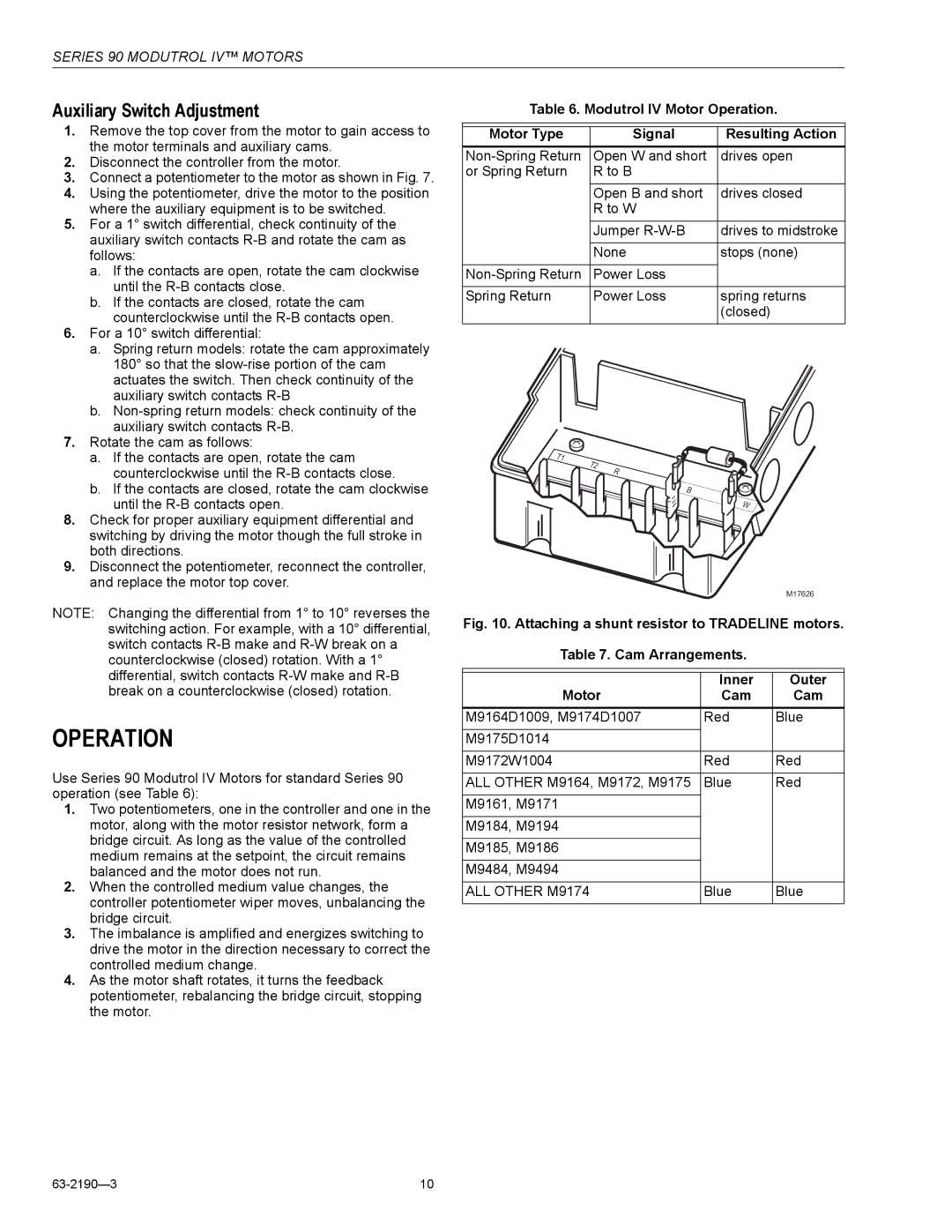
Fig. 10. Attaching a shunt resistor to TRADELINE motors.

Table 7. Cam Arrangements.

Motor

Inner

Outer

Cam

Cam

M9164D1009, M9174D1007

Red

Blue

M9175D1014


M9172W1004

Red

Red


ALL OTHER M9164, M9172, M9175

Blue

Red


M9161, M9171


M9184, M9194


M9185, M9186


M9484, M9494


ALL OTHER M9174

Blue

Blue


63-2190—3

10

Page 10
Image 10
Honeywell Series 90 specifications Operation, Auxiliary Switch Adjustment

Series 90 specifications

The Honeywell Series 90 is a prominent line of control systems tailored for industrial applications, enhancing efficiency, reliability, and adaptability in process automation. Designed to meet the evolving demands of various industries, the Series 90 is renowned for its versatility, scalability, and robust performance.

One of the main features of the Honeywell Series 90 is its modular architecture, which allows users to configure and expand their systems easily. This flexibility ensures that the system can grow alongside the needs of an organization, whether it involves adding new control loops, expanding I/O points, or integrating with existing systems. The ability to seamlessly expand and modify the system makes it particularly appealing to users in dynamic environments.

The Series 90 is equipped with advanced control technologies that elevate process efficiency. With its powerful control algorithms, it can handle complex processes and deliver superior control performance. In addition, the system supports multiple communication protocols, facilitating easy integration with other devices and systems. This interoperability is key for operations that depend on precise data transfer and real-time monitoring.

Reliability is critical in industrial applications, and the Honeywell Series 90 is designed with this in mind. The system boasts high availability through redundant components, ensuring continuous operation even during maintenance or unexpected failures. Built-in self-diagnostics help identify issues proactively, reducing downtime and enhancing overall system reliability.

User-friendliness is another characteristic that sets the Honeywell Series 90 apart. The intuitive interface, along with comprehensive configuration tools, simplifies system setup and operation for both experienced engineers and newcomers. Enhanced visualization capabilities allow operators to monitor and control processes effectively, improving decision-making and response times.

Furthermore, the Honeywell Series 90 is equipped with robust security features to protect against cyber threats. With the increased connectivity of industrial systems, security has become paramount, and Honeywell has prioritized safeguarding its clients' operations.

In summary, the Honeywell Series 90 stands out in the realm of industrial control systems due to its modular design, advanced control technologies, reliability, user-friendly interface, and robust security measures. These features make it an ideal solution for organizations seeking to enhance their process automation capabilities while ensuring longevity and adaptability in a competitive landscape.