|
|
| GAS LEAK DETECTOR INSTALLATION & USER GUIDE |
|
|
|
|
|
|
|
|
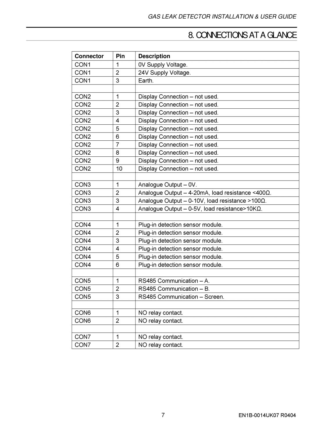
| 8. CONNECTIONS AT A GLANCE |
|
|
|
|
|
|
| Connector | Pin | Description |
|
| CON1 | 1 | 0V Supply Voltage. |
|
| CON1 | 2 | 24V Supply Voltage. |
|
| CON1 | 3 | Earth. |
|
|
|
|
|
|
| CON2 | 1 | Display Connection – not used. |
|
| CON2 | 2 | Display Connection – not used. |
|
| CON2 | 3 | Display Connection – not used. |
|
| CON2 | 4 | Display Connection – not used. |
|
| CON2 | 5 | Display Connection – not used. |
|
| CON2 | 6 | Display Connection – not used. |
|
| CON2 | 7 | Display Connection – not used. |
|
| CON2 | 8 | Display Connection – not used. |
|
| CON2 | 9 | Display Connection – not used. |
|
| CON2 | 10 | Display Connection – not used. |
|
|
|
|
|
|
| CON3 | 1 | Analogue Output – 0V. |
|
| CON3 | 2 | Analogue Output – |
|
| CON3 | 3 | Analogue Output – |
|
| CON3 | 4 | Analogue Output – |
|
|
|
|
|
|
| CON4 | 1 |
| |
| CON4 | 2 |
| |
| CON4 | 3 |
| |
| CON4 | 4 |
| |
| CON4 | 5 |
| |
| CON4 | 6 |
| |
|
|
|
|
|
| CON5 | 1 | RS485 Communication – A. |
|
| CON5 | 2 | RS485 Communication – B. |
|
| CON5 | 3 | RS485 Communication – Screen. |
|
|
|
|
|
|
| CON6 | 1 | NO relay contact. |
|
| CON6 | 2 | NO relay contact. |
|
|
|
|
|
|
| CON7 | 1 | NO relay contact. |
|
| CON7 | 2 | NO relay contact. |
|
7 |