V4062A,B,D HI-LO-OFF FLUID POWER GAS VALVE ACTUATOR

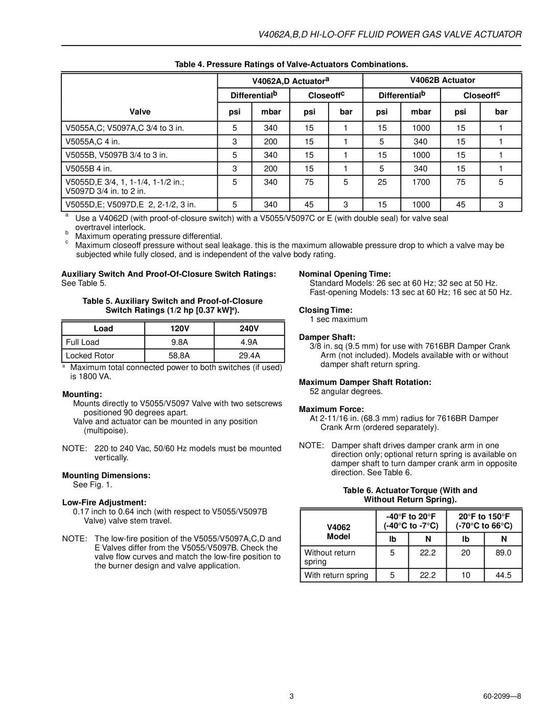
Table 4. Pressure Ratings of Valve-Actuators Combinations.


V4062A,D Actuatora


V4062B Actuator


Differentialb

Closeoffc

Differentialb

Closeoffc

Valve

psi

mbar

psi


bar

psi

mbar

psi

bar


V5055A,C; V5097A,C 3/4 to 3 in.

5

340

15


1

15

1000

15

1


V5055A,C 4 in.

3

200

15


1

5

340

15

1


V5055B, V5097B 3/4 to 3 in.

5

340

15


1

15

1000

15

1


V5055B 4 in.

3

200

15


1

5

340

15

1


V5055D,E 3/4, 1, 1-1/4, 1-1/2 in.;

5

340

75


5

25

1700

75

5

V5097D 3/4 in. to 2 in.


V5055D,E; V5097D,E 2, 2-1/2, 3 in.

5

340

45


3

15

1000

45

3


aUse a V4062D (with proof-of-closure switch) with a V5055/V5097C or E (with double seal) for valve seal overtravel interlock.

bMaximum operating pressure differential.

cMaximum closeoff pressure without seal leakage. this is the maximum allowable pressure drop to which a valve may be subjected while fully closed, and is independent of the valve body rating.

Auxiliary Switch And Proof-Of-Closure Switch Ratings:

See Table 5.

Table 5. Auxiliary Switch and Proof-of-Closure

Switch Ratings (1/2 hp [0.37 kW]a).


Load

120V

240V


Full Load

9.8A

4.9A


Locked Rotor

58.8A

29.4A


aMaximum total connected power to both switches (if used) is 1800 VA.

Mounting:

Mounts directly to V5055/V5097 Valve with two setscrews positioned 90 degrees apart.

Valve and actuator can be mounted in any position (multipoise).

NOTE: 220 to 240 Vac, 50/60 Hz models must be mounted vertically.

Mounting Dimensions:

See Fig. 1.

Low-Fire Adjustment:

0.17inch to 0.64 inch (with respect to V5055/V5097B Valve) valve stem travel.

NOTE: The low-fire position of the V5055/V5097A,C,D and E Valves differ from the V5055/V5097B. Check the valve flow curves and match the low-fire position to the burner design and valve application.

Nominal Opening Time:

Standard Models: 26 sec at 60 Hz; 32 sec at 50 Hz.

Fast-opening Models: 13 sec at 60 Hz; 16 sec at 50 Hz.

Closing Time:

1 sec maximum

Damper Shaft:

3/8 in. sq (9.5 mm) for use with 7616BR Damper Crank Arm (not included). Models available with or without damper shaft return spring.

Maximum Damper Shaft Rotation:

52 angular degrees.

Maximum Force:

At 2-11/16 in. (68.3 mm) radius for 7616BR Damper Crank Arm (ordered separately).

NOTE: Damper shaft drives damper crank arm in one direction only; optional return spring is available on damper shaft to turn damper crank arm in opposite direction. See Table 6.

Table 6. Actuator Torque (With and

Without Return Spring).


-40°F to 20°F

20°F to 150°F

V4062

(-40°C to -7°C)

(-70°C to 66°C)

Model

lb

N

lb

N


Without return

5

22.2

20

89.0

spring


With return spring

5

22.2

10

44.5


3

60-2099—8

Page 3
Image 3
Honeywell V4062B Psi Bar, Auxiliary Switch And Proof-Of-Closure Switch Ratings, Mounting Dimensions, Closing Time

V4062C, V4062B specifications

The Honeywell V4062B and V4062C are advanced zone valves that play a critical role in modern heating and cooling systems. Designed for use with hot water heating systems, these valves provide efficient control of fluid flow in residential and commercial HVAC applications.

The V4062B series features robust construction and is designed to handle a range of installation environments. It operates on a two-wire system, simplifying wiring and installation. The valve is typically used for applications involving fan coil units, radiant heating, and other hydronic systems. With a high flow capacity, the V4062B allows effective temperature regulation throughout various zones, ensuring optimal comfort in any setting.

On the other hand, the V4062C model brings additional functionalities. This variant includes a microprocessor-based system that enhances control capabilities. The smart technology embedded in the V4062C enables precise modulation of water flow based on real-time temperature readings. This innovative feature significantly improves energy efficiency, ultimately leading to lower operating costs.

Both the V4062B and V4062C models incorporate durable materials to guarantee longevity and reliability. The valve bodies are crafted from corrosion-resistant brass, ensuring a prolonged lifespan even in challenging environments. Additionally, they are designed with a union connection that facilitates easy installation and maintenance, reducing labor costs and downtime.

An important characteristic shared by both models is their compatibility with standard 24 VAC systems, allowing them to seamlessly integrate with existing HVAC setups. Moreover, they feature a compact design, which is particularly advantageous in installations with limited space. This adaptability makes them a popular choice among HVAC professionals seeking reliable and efficient solutions.

Both the V4062B and V4062C series valves are equipped with manual override features, enabling users to adjust flow manually when needed. This can be especially useful in emergency situations or during system maintenance.

In summary, the Honeywell V4062B and V4062C valves stand out for their reliability, efficiency, and advanced technology. With their durable construction and smart control features, they serve as efficient solutions for managing zoning within heating and cooling systems, promising comfort and energy savings for any property.