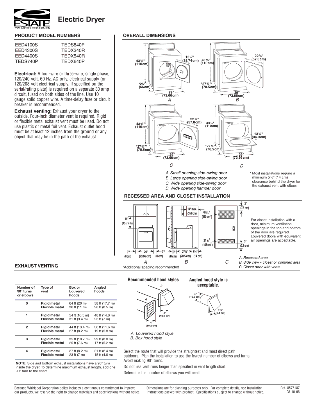
EED4300S, EED4100S, TEDX640P, EED4400S, TEDS840P specifications
The Estate TEDX340R, TEDX540R, TEDS740P, TEDS840P, and EED4400S represent a cutting-edge range of estate utility vehicles designed for both performance and practicality. Each model boasts unique features, technologies, and characteristics tailored to meet various user needs, from everyday tasks to specialized operations.Starting with the TEDX340R, this model emphasizes agility and maneuverability. Equipped with a robust yet lightweight chassis, the TEDX340R is powered by an efficient engine that provides quick acceleration and excellent fuel efficiency. Key features include a spacious cargo bed designed for easy loading and unloading, as well as superior suspension systems for a smooth ride over uneven terrain. The advanced braking system ensures safety, making it suitable for both novice users and experienced operators.
Next, the TEDX540R builds upon the strengths of the 340R, offering enhanced power and versatility. Its larger engine delivers increased towing capacity, making it ideal for hauling heavier loads. The TEDX540R also introduces an ergonomic cabin design with adjustable seating and an intuitive dashboard layout, providing maximum comfort for long hours of operation. Additionally, this model includes innovative technologies such as Bluetooth connectivity and a GPS navigation system, allowing users to stay connected while on the move.
The TEDS740P takes functionality a step further by incorporating specialized features tailored for agricultural and commercial applications. This model comes equipped with high-traction tires and all-wheel drive capabilities, making it a powerful choice for off-road tasks. Its advanced hydraulic lift system facilitates seamless attachment of various implements, enhancing productivity in agricultural settings. The spacious cab is designed with noise reduction technology, offering a quieter work environment.
For those seeking a premium model, the TEDS840P offers top-of-the-line performance and luxury. Enhanced with luxurious upholstery and premium sound systems, the TEDS840P prioritizes user comfort. This model utilizes eco-friendly technologies, including an energy-efficient engine and reduced emissions systems, making it a responsible choice for environmentally conscious users. Furthermore, it features advanced safety systems, including stability control and collision avoidance systems.
Finally, the EED4400S represents a versatile electric option within the range. Offering low running costs and zero emissions, this model is perfect for urban environments and eco-sensitive areas. The EED4400S features regenerative braking to extend battery life, paired with a robust battery management system that maximizes efficiency. Its compact size allows for easy maneuverability in tight spaces, making it ideal for tasks in crowded locations.
Overall, the Estate TEDX340R, TEDX540R, TEDS740P, TEDS840P, and EED4400S offer a diverse selection of estate utility vehicles, catering to a diverse range of applications while ensuring performance, comfort, and sustainability. Each model is thoughtfully engineered to provide reliable solutions for both personal and professional needs.