
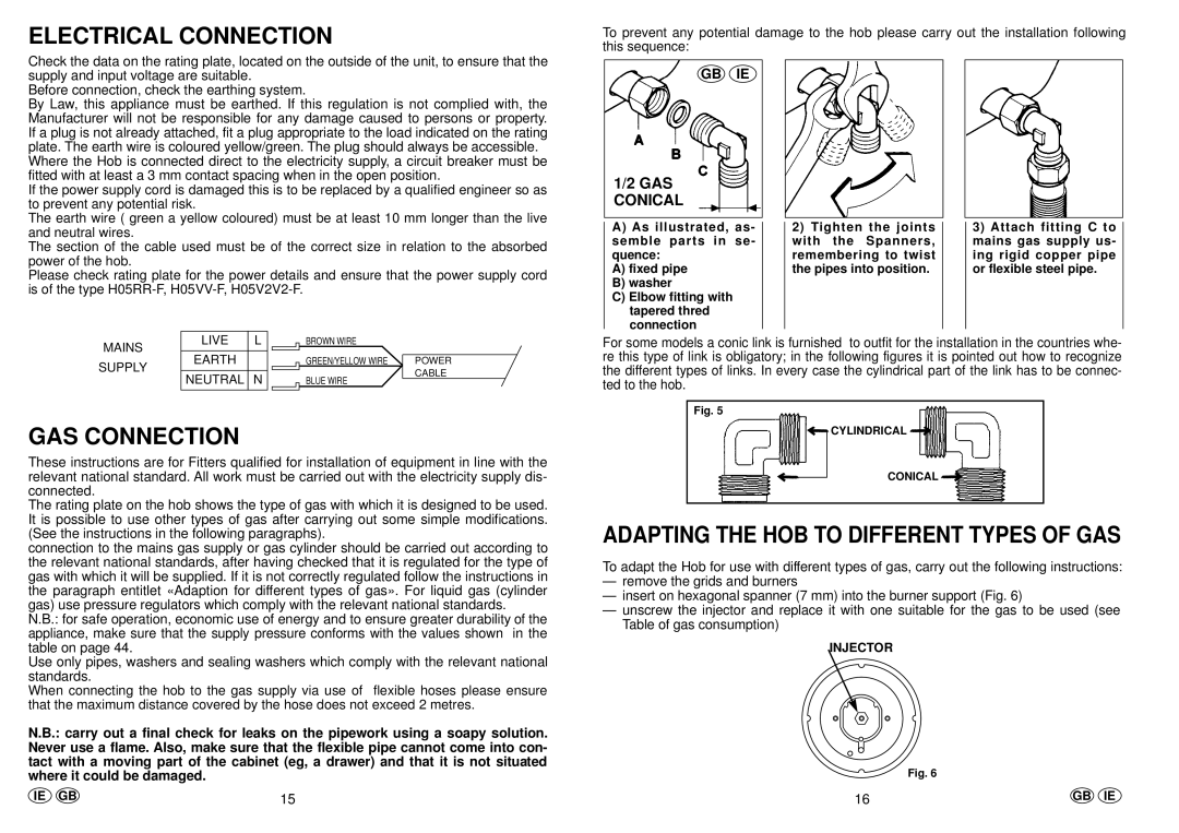
PL73, PL74 specifications
The Hoover PL74 and PL73 are advanced vacuum cleaner models that exemplify Hoover's commitment to blending power, efficiency, and user-friendly design. These models are tailored for those seeking a reliable cleaning solution without compromising on performance or convenience.One of the standout features of the Hoover PL74 and PL73 is their impressive suction power, enabled by Hoover’s innovative motor technology. This technology not only ensures deep cleaning across various surfaces, including carpets and hard floors, but also enhances the longevity and durability of the vacuum. The models employ a cyclonic filtration system which separates dirt from air, preventing clogging and maintaining suction strength over time.
Another key characteristic of the PL74 and PL73 is their lightweight design. Weighing significantly less than many comparable models, these vacuums provide unparalleled maneuverability. Users can easily carry them up and down stairs or around the home without experiencing fatigue. This is complemented by a user-friendly handle and a flexible hose that enhances reach, allowing for easy cleaning of hard-to-reach areas like under furniture and along edges.
The Hoover PL74 and PL73 also incorporate advanced filtration systems that capture allergens and fine dust particles, making them an excellent choice for allergy sufferers. The HEPA filters used in these models ensure that air expelled back into the environment is cleaner than the air taken in, promoting a healthier home atmosphere.
For added convenience, both models come equipped with a range of attachments, including a crevice tool, dusting brush, and upholstery nozzle. These attachments are beneficial for tailored cleaning tasks, from detailed cleaning of furniture and delicate surfaces to targeted suction in narrow spaces.
Ease of use is further enhanced by features such as a large dust bin that minimizes the frequency of emptying, LED indicators that signal when the dust bin is full, and an easy-to-use power control system that allows users to adjust suction power as needed.
In summary, the Hoover PL74 and PL73 vacuum cleaners combine powerful suction, lightweight design, and advanced filtration technologies to deliver outstanding cleaning performance. These features make them not only effective cleaning tools but also convenient and practical choices for modern homes. Whether tackling pet hair, allergens, or everyday dirt, these Hoover models stand out as reliable solutions for maintaining a clean and healthy living environment.