Instructions for the installer
GB
Installation
These Instrnctions are for the qualified technician, as a guide to the installation, adjustment and maintenance, according to the laws and standards in force. Any of these operations must always be canied out when the appliance has been disconnected from the electric system.
Positioning (Fig. 4-4a)
The appliance can be fitted into a working area as illustrated on the figure. Apply the seal supplied over the whole perimeter of the working area.
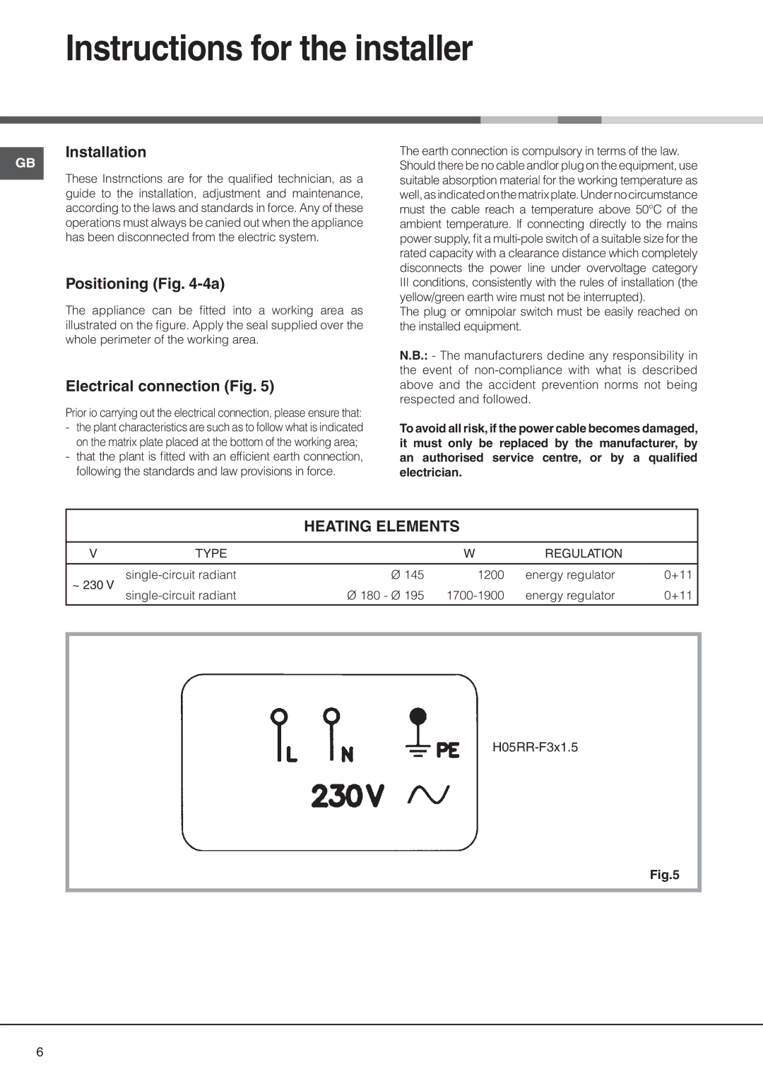
Electrical connection (Fig. 5)
Prior io carrying out the electrical connection, please ensure that:
-the plant characteristics are such as to follow what is indicated on the matrix plate placed at the bottom of the working area;
-that the plant is fitted with an efficient earth connection, following the standards and law provisions in force.
The earth connection is compulsory in terms of the law. Should there be no cable andlor plug on the equipment, use suitable absorption material for the working temperature as well,asindicatedonthematrixplate.Undernocircumstance must the cable reach a temperature above 50°C of the ambient temperature. lf connecting directly to the mains power supply, fit a
IIIconditions, consistently with the rules of installation (the yellow/green earth wire must not be interrupted).
The plug or omnipolar switch must be easily reached on the installed equipment.
N.B.: - The manufacturers dedine any responsibility in the event of
To avoid all risk, if the power cable becomes damaged, it must only be replaced by the manufacturer, by an authorised service centre, or by a qualified electrician.
HEATING ELEMENTS
V | TYPE |
| W | REGULATION |
|
|
|
|
|
|
|
~ 230 V | Ø 145 | 1200 | energy regulator | 0+11 | |
Ø 180 - Ø 195 | energy regulator | 0+11 |
Fig.5
6