Installation
The following instructions are intended for the installer so that the installation and maintenance procedures may be followed in the most professional and expert manner possible. Important:
Disconnect the appliance from the electrical supply before performinganymaintenanceorrepair.
Positioning the Hob
Important: this unit may be installed and used only in permanently ventilated rooms in accordance with British Standard Codes Of Practice: B.S. 6172 / B.S. 5440, Par. 2 and B.S.6891 Current Editions.The following requirements must be observed:
a)The room must be fitted with a ventilation system which vents smoke and gases from combustion to the outside.This must be done by means of a hood or electric ventilator that turns on automatically each time the hob is operated.
In a chimney stack or branched flue. | Directly to the Outside |
(exclusively for cooking appliances)
b)Theroommusthaveanairflowtoallowforpropercombustion. Thismustbe2m3³/hperkWofinstalledpower.Theairflowcan be created using an enclosed vent with an inner cross section of at least 100 cm² which must not be able to be blocked. I the appliance does not have a flame failure device, the vent must haveaninternalcrosssectionof200cm3³(Fig. A). Alternatively the room in which the hob is situated can be vented indirectly through ventilation ducts as specified above, as long as the adjacent room is not a shared area, a bedroom or present any
riskoffire(Fig. B).
|
| Detail A |
|
|
|
| Adjacent | Room to be | |||||||
|
|
|
|
|
|
|
|
|
|
|
| Room | Vented | ||
|
|
|
|
|
|
|
|
|
|
|
|
|
|
|
|
|
|
|
|
|
|
|
|
|
|
|
|
|
|
|
|
|
|
|
|
|
|
|
|
|
|
|
|
|
|
|
|
|
|
|
|
|
|
|
|
|
|
|
|
|
|
|
|
|
|
|
|
|
|
|
|
|
|
|
|
|
|
|
|
|
|
|
|
|
|
|
|
|
|
|
|
|
|
|
|
|
|
|
|
|
|
|
|
|
|
|
|
|
|
|
|
|
|
|
|
|
|
|
|
|
|
|
|
|
|
|
|
A
Examples of ventilation holes | Enlarging the ventilation slot |
for comburant air. | between window and floor. |
Fig.A | Fig.B |
c)Intensiveandprolongeduseoftheappliancemaynecessitate supplemental ventilation, e.g. opening a window or increasing the power of the air intake system (if present).
d)Liquidifiedpetroleumgasesareheavierthanairand,asaresult, settle downwards. Rooms in which LPG tanks are installed mustbefittedwithventilationopeningstotheoutsideinorderto allow the gas to escape in the event of a leak. Therefore, LPG tanks, whether empty or partially full, must not be installed or storedinroomsorspacesbelowgroundlevel(cellars,ect.).Itis also a good idea to keep only the tank currently being used in theroom,makingsurethatitisnotnearsourcesofheat(ovens, fireplaces,stoves,etc.)thatcouldraisetheinternaltemperature of the tank above 50°C.
Installation of built-in hobs
The gas hobs are prepared with protection degree against excessive heating of type X, the appliance can therefore be installed next to cabinets, provided the height does not exceed that of the hob. For a correct installation of the cooking hob the following precautions must be followed:
a)The hob may be located in a kitchen, a kitchen/diner or bed sitting room, but not in a bathroom or shower room.
b)The furniture standing next to the unit, that is higher than the working boards, must be placed at least 110mm from the edge of the board.
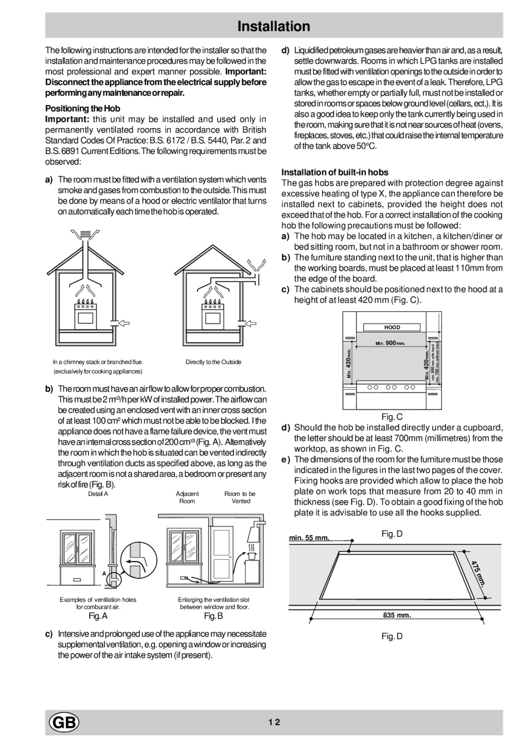
c)The cabinets should be positioned next to the hood at a height of at least 420 mm (Fig. C).
HOOD
| Min. 900 mm. | min. 650 mm. with hood min. 700 mm. without hood |
Min. 420 mm. | Min. 420 mm. |
Fig. C
d)Should the hob be installed directly under a cupboard, the letter should be at least 700mm (millimetres) from the worktop, as shown in Fig. C.
e)The dimensions of the room for the furniture must be those indicated in the figures in the last two pages of the cover. Fixing hooks are provided which allow to place the hob plate on work tops that measure from 20 to 40 mm in thickness (see Fig. D). To obtain a good fixing of the hob plate it is advisable to use all the hooks supplied.
min. 55 mm. | Fig. D |
| |
|
|
|
|
835 mm.
Fig. D
1 2